Information governor assy, mec
Rating:
KIT List:
| Governor assy, mec | 1908900170 |
| Governor assy, mec | 1908900170 |
Scheme ###:
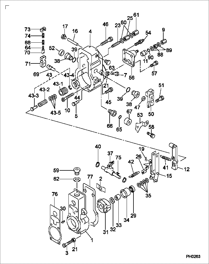
| 000. | [01] | 19080-07110 | GOVERNOR ASSY, MEC | |
| 001. | [01] | 09081-00660 | HOUSING SUB-ASSY, | |
| 002. | [01] | 09087-80030 | PLATE | |
| 003. | [01] | 09102-40120 | SCREW, ADJUSTING | |
| 004. | [01] | 09101-11670 | COVER, GOVERNOR | |
| 005. | [01] | 09101-40090 | PIN, STOP | |
| 007. | [01] | 09102-40031 | SCREW, ADJUSTING | 09102-40031 |
| 009. | [01] | 09103-10151 | NUT, CAP | 09103-10151 |
| 010. | [01] | 09100-60150 | SCREW, STROKE ADJU | 09100-60150 |
| 011. | [01] | 09094-40310 | BUSHING | 09094-40310 |
| 012. | [01] | 09090-10150 | LEVER, TENSION | |
| 015. | [01] | 09093-00041 | LEVER ASSY, CONTRO | |
| 016. | [01] | 09098-90010 | SHAFT, LEVER SUPPO | 09098-90010 |
| 017. | [02] | 09099-10010 | PLUG, SCREW | 09099-10010 |
| 019. | [01] | 90400-02101 | PIN, SPLIT | 90400-02101 |
| 021. | [02] | 94805-30051 | NUT, HEXAGON, W/HO | 94805-30051 |
| 023. | [01] | 09056-00150 | CAPSULE, FULL STOP | |
| 025. | [01] | 09092-30060 | NUT, ADAPTER LOCK | |
| 026. | [01] | 09097-00170 | SHACKLE ASSY | 09097-00170 |
| 029. | [01] | 94910-00010 | BEARING, BALL | 85264-00028 |
| 030. | [01] | 94913-00050 | KEY, WOODRUFF | 94913-00050 |
| 031. | [01] | 09084-00660 | FLYWEIGHT ASSY | |
| 032. | [01] | 94901-50500 | WASHER, SPRING | 94901-50500 |
| 033. | [01] | 09084-40010 | NUT, ROUND | 85264-00026 |
| 034. | [01] | 09086-10010 | SLEEVE, GOVERNOR | 85264-00027 |
| 035. | [4C] | 94901-34100 | WASHER, PLATE, SK | 94901-34100 |
| 035. | [4C] | 94901-34090 | WASHER, PLATE, SK | 94901-34090 |
| 035. | [4C] | 94901-34080 | WASHER, PLATE, SK | 94901-34080 |
| 035. | [4C] | 94901-34070 | WASHER, PLATE, SK | 94901-34070 |
| 035. | [4C] | 94901-34060 | WASHER, PLATE, SK | 94901-34060 |
| 037. | [01] | 09088-00140 | LEVER ASSY, SWIEVE | |
| 038. | [02] | 09089-20080 | BUSHING, LEVER | 09089-20080 |
| 039. | [02] | 90801-20160 | O-RING | 90801-20160 |
| 040. | [02] | 94907-10090 | WASHER, SNAP | 85264-00037 |
| 041. | [01] | 09099-20410 | SPRING, SPEED CONT | |
| 042. | [01] | 09099-30010 | SPRING, START | 09099-30010 |
| 043. | [01] | 09091-01410 | ADAPTER ASSY | |
| 043-001. | [01] | 09091-10010 | SCREW, ADPTER | 09091-10010 |
| 043-002. | [01] | 09091-82120 | SPRING, MECHANICAL | |
| 043-003. | [01] | 09091-90010 | ADAPTER | 09091-90010 |
| 043-004. | [01] | 09089-40010 | E-RING | 09089-40010 |
| 043-005. | [1C] | 94901-33880 | WASHER, PLATE, SK | 94901-33880 |
| 043-005. | [1C] | 94901-34020 | WASHER, PLATE, SK | 94901-34020 |
| 043-005. | [1C] | 94901-34030 | WASHER, PLATE, SK | 94901-34030 |
| 043-005. | [1C] | 94901-34040 | WASHER, PLATE, SK | 94901-34040 |
| 044. | [01] | 09092-30011 | NUT, ADAPTER LOCK | 85264-00044 |
| 045. | [04] | 94904-71760 | BOLT, W/WASHER | 94904-71760 |
| 046. | [02] | 94904-71750 | BOLT, W/WASHER | 94904-71750 |
| 047. | [01] | 94915-00210 | SEAL, OIL | 94915-00210 |
| 050. | [01] | 09107-11930 | LEVER, ADJUSTING | |
| 051. | [01] | 94904-71190 | BOLT, W/WASHER | 94904-71190 |
| 052. | [01] | 09109-40060 | CAP, LEVER | 09109-40060 |
| 053. | [01] | 09109-01160 | LEVER SUB-ASSY, ST | |
| 054. | [02] | 94904-32250 | BOLT, STUD | |
| 056. | [01] | 09105-00491 | PLATE SUB-ASSY, CO | |
| 057. | [02] | 94904-72701 | BOLT, W/WASHER | |
| 058. | [01] | 91418-06161 | BOLT, W/WASHER | 91418-06161 |
| 059. | [01] | 09116-70050 | PLUG, SCREW | 09116-70050 |
| 060. | [02] | 09024-10010 | WASHER, AIR BLEEDE | MM500486 |
| 061. | [01] | 09103-10030 | NUT, CAP | 09103-10030 |
| 062. | [01] | 94901-81550 | WASHER, COPPER PLA | |
| 063. | [01] | 94906-21270 | PACKING, RUBBER PL | 94906-21270 |
| 064. | [01] | 09103-80040 | SPRING, B | 09103-80040 |
| 065. | [01] | 94914-00130 | O-RING | 85264-00073 |
| 066. | [01] | 09101-60360 | BUSHING, BEARING | |
| 067. | [01] | 09104-30010 | COVER, SPRING | 85264-00075 |
| 068. | [01] | 09103-80050 | SPRING, B | 09103-80050 |
| 069. | [01] | 09103-50240 | SHAFT, MECHANICAL | 09103-50240 |
| 070. | [01] | 09103-60010 | CUP, SPRING | 85264-00065 |
| 071. | [01] | 09103-40161 | LEVER, SUPPORT | |
| 073. | [01] | 09103-30030 | PLATE, CAP | 09103-30030 |
| 074. | [01] | 09103-80030 | SPRING, B | 09103-80030 |
| 075. | [01] | 94913-00030 | KEY, WOODRUFF | 94913-00031 |
| 076. | [01] | 09082-30460 | GASKET | |
| 077. | [01] | 09082-30420 | GASKET | |
| 088. | [01] | 94905-03390 | NUT, HEXAGON | 94905-03390 |
| 089. | [02] | 94901-81020 | WASHER, COPPER PLA | 94901-81020 |
| 090. | [01] | 90801-10120 | O-RING | EZ40058081 |
Include in #3:
09200-05620
as GOVERNOR ASSY, MEC
19080-07110
Cross reference number
| Part num | Firm num | Firm | Name |
| 19080-07110 | GOVERNOR ASSY, MEC |
Information:
1. Install the engine on tool (C). Fasten it in position at the flywheel end as shown.2. Remove bridges (1) and the seals. 3. Remove connecting rod bearing caps (2) and (3). Be sure the connecting rods, connecting rod caps and bearings are labeled so the parts can be matched at assembly. Be sure the location is marked on the main bearing caps before they are removed. The stamped location number is toward the camshaft. 4. Remove five main bearing caps (4). Remove the bearings from the main bearing caps, and remove the thrust washers from the center main bearing cap. Put identification marks on the bearings as to their location in the engine.5. Remove the connecting rod bolts, and push the pistons to the top of their stroke. Do not damage the crankshaft journals with the connecting rod bolts. 6. Remove the two upper thrust bearings (5). 7. Fasten a nylon strap and hoist to the crankshaft. The weight of the crankshaft is 27 kg (60 lb.).8. Carefully lift crankshaft (6) out of the engine, and store the crankshaft in a safe place. 9. Remove main bearing upper halves (7) from the engine block, and connecting rod bearing upper halves (8) from the connecting rods. Tape each bearing half to its respective lower bearing half. 10. Remove gear (9) from the crankshaft with tooling (A). Remove the key.11. Use tool (B) and quick dry solvent to clean the oil passages in the crankshaft.12. Clean the passage with quick dry solvent, and dry with compressed air.13. Inspect the crankshaft journals and thrust flange. See Engine Specifications.Install Crankshaft
1. Be sure all parts are clean.2. Install key (2) on crankshaft (3).3. Put crankshaft gear (1) in position with the timing mark toward the outside.
Original Crankshaft Replacement part service crankshafts may differ in appearance from the original crankshaft, but are functionally the same. 4. If the original main bearings are to be used, install bearing upper halves (4) in their original location. If new bearings are to be used, install the main bearing upper halves. Do not put oil on the bearings at this time. 5. Fasten a nylon strap and hoist to the crankshaft (5), and carefully put the crankshaft in place in the main bearing upper halves.6. Check main bearing clearances. Follow the procedures in Specifications.7. Fasten a nylon strap and hoist to the crankshaft, and lift the crankshaft so clean engine oil can be put on the bearing upper halves. 8. Install new thrust washers (6) on each side of the center main bearing location in the engine block. Be sure the bearing surface is toward the crankshaft and the smooth surface is toward the engine block. 9. Put new thrust washers (8) on each side of center main bearing cap (7). Be sure the tabs