Information governor assy, mec
Rating:
KIT List:
| Governor assy, mec | No Application |
| Governor assy, mec | No Application |
| Governor assy, mec | No Application |
| Governor assy, mec | No Application |
| Governor assy, mec | No Application |
Scheme ###:
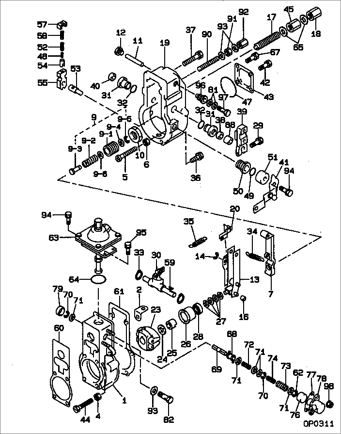
| 000. | [01] | 19080-04540 | GOVERNOR ASSY, MEC | |
| 001. | [01] | 09081-00620 | HOUSING SUB-ASSY, | |
| 002. | [01] | 09087-80200 | PLATE | |
| 004. | [01] | 94805-30051 | NUT, HEXAGON, W/HO | |
| 005. | [01] | 09100-60170 | SCREW, STROKE ADJU | |
| 006. | [01] | 94905-03390 | NUT, HEXAGON | |
| 007. | [01] | 09090-10150 | LEVER, TENSION | |
| 009. | [01] | 09091-00570 | ADAPTER ASSY | |
| 009-001. | [01] | 09091-10010 | SCREW, ADPTER | |
| 009-002. | [01] | 09091-80131 | SPRING, MECHANICAL | |
| 009-003. | [01] | 09091-90010 | ADAPTER | |
| 009-004. | [01] | 09092-10010 | WASHER | |
| 009-005. | [01] | 09089-40010 | E-RING | |
| 009-006. | [2C] | 94901-33880 | WASHER, PLATE, SK | |
| 009-006. | [2C] | 94901-34020 | WASHER, PLATE, SK | |
| 009-006. | [2C] | 94901-34030 | WASHER, PLATE, SK | |
| 009-006. | [2C] | 94901-34040 | WASHER, PLATE, SK | |
| 009-006. | [2C] | 94901-37880 | WASHER, PLATE, SK | |
| 010. | [01] | 09092-30011 | NUT, ADAPTER LOCK | |
| 011. | [01] | 09098-90060 | SHAFT, LEVER SUPPO | |
| 012. | [01] | 09099-10090 | PLUG, SCREW | |
| 013. | [01] | 09093-00720 | LEVER ASSY, CONTRO | |
| 014. | [01] | 09089-40010 | E-RING | |
| 016. | [01] | 09104-60010 | SLIDER, SUPPORTING | |
| 017. | [01] | 09056-00150 | CAPSULE, FULL STOP | |
| 018. | [01] | 09103-10030 | NUT, CAP | |
| 019. | [01] | 09101-01240 | COVER SUB-ASSY, GO | |
| 020. | [01] | 09097-00390 | SHACKLE ASSY | |
| 023. | [01] | 09084-00720 | FLYWEIGHT ASSY | |
| 024. | [01] | 94901-50500 | WASHER, SPRING | |
| 025. | [01] | 09084-40010 | NUT, ROUND | |
| 026. | [01] | 09086-10010 | SLEEVE, GOVERNOR | |
| 027. | [4C] | 94901-34060 | WASHER, PLATE, SK | |
| 027. | [4C] | 94901-34070 | WASHER, PLATE, SK | |
| 027. | [4C] | 94901-34080 | WASHER, PLATE, SK | |
| 027. | [4C] | 94901-34090 | WASHER, PLATE, SK | |
| 027. | [4C] | 94901-34100 | WASHER, PLATE, SK | |
| 028. | [01] | 94910-00010 | BEARING, BALL | |
| 029. | [01] | 94904-74770 | BOLT, W/WASHER | |
| 030. | [01] | 09088-00140 | LEVER ASSY, SWIEVE | |
| 031. | [02] | 09089-20080 | BUSHING, LEVER | |
| 032. | [02] | 94914-05760 | O-RING | |
| 033. | [02] | 94907-10090 | WASHER, SNAP | |
| 034. | [01] | 09099-20410 | SPRING, SPEED CONT | |
| 035. | [01] | 09099-30280 | SPRING, START | |
| 036. | [04] | 94904-74810 | BOLT, W/WASHER | |
| 037. | [02] | 94904-76270 | BOLT, W/WASHER | |
| 038. | [01] | 94915-02690 | SEAL, OIL | |
| 039. | [01] | 09107-11420 | LEVER, ADJUSTING | |
| 040. | [01] | 09109-40060 | CAP, LEVER | |
| 041. | [01] | 09109-01450 | LEVER SUB-ASSY, ST | |
| 042. | [02] | 94904-74780 | BOLT, W/WASHER | |
| 043. | [01] | 09105-10420 | PLATE, COVER | |
| 044. | [01] | 09102-40031 | SCREW, ADJUSTING | |
| 045. | [01] | 09092-30060 | NUT, ADAPTER LOCK | |
| 047. | [01] | 94906-21270 | PACKING, RUBBER PL | |
| 048. | [01] | 09103-80040 | SPRING, B | |
| 049. | [01] | 94914-06170 | O-RING | |
| 050. | [01] | 09101-60020 | BUSHING, BEARING | |
| 050. | [01] | 09101-60360 | BUSHING, BEARING | |
| 051. | [01] | 09104-30010 | COVER, SPRING | |
| 052. | [01] | 09103-80050 | SPRING, B | |
| 053. | [01] | 09103-50240 | SHAFT, MECHANICAL | |
| 054. | [01] | 09103-60010 | CUP, SPRING | |
| 055. | [01] | 09103-40130 | LEVER, SUPPORT | |
| 057. | [01] | 09103-30030 | PLATE, CAP | |
| 058. | [01] | 09103-80030 | SPRING, B | |
| 059. | [01] | 94913-00030 | KEY, WOODRUFF | |
| 060. | [01] | 09011-90160 | GASKET, PUMP BODY | |
| 061. | [01] | 09082-30022 | GASKET | |
| 062. | [01] | 09089-40070 | E-RING | |
| 063. | [01] | 19260-00650 | COMPENSATOR SUB-AS | |
| 064. | [01] | 94914-04670 | O-RING | |
| 065. | [02] | 09024-10010 | WASHER, AIR BLEEDE | |
| 067. | [02] | 94904-74790 | BOLT, W/WASHER | |
| 068. | [01] | 19265-00010 | LEVER SUB-ASSY, FO | |
| 069. | [01] | 19265-30010 | SHAFT, LEVER | |
| 070. | [02] | 90577-05000 | E-RING | |
| 071. | [05] | 94901-33150 | WASHER, PLATE, SK | |
| 072. | [01] | 19265-40010 | SPRING, CANCEL | |
| 073. | [01] | 19264-50010 | SPRING, RETURN, A | |
| 074. | [01] | 19264-60010 | SPRING, RETURN, B | |
| 076. | [01] | 19264-30011 | PISTON | |
| 077. | [01] | 19264-80010 | GASKET | |
| 078. | [01] | 19264-10011 | HOUSING, START EXC | |
| 079. | [01] | 09109-40080 | CAP, LEVER | |
| 081. | [02] | 09024-80010 | WASHER, DRAIN SCRE | |
| 082. | [01] | 09116-70110 | PLUG, SCREW | |
| 088. | [01] | 94919-24580 | COLLAR, STEEL | |
| 090. | [01] | 09082-10171 | STOPPER | |
| 091. | [01] | 94905-30140 | NUT, HEXAGON, W/ H | |
| 092. | [01] | 09103-10042 | NUT, CAP | |
| 093. | [03] | 94901-81020 | WASHER, COPPER PLA | |
| 094. | [03] | 94904-74920 | BOLT, W/WASHER | |
| 095. | [02] | 94904-76260 | BOLT, W/WASHER | |
| 096. | [01] | 09012-10270 | NIPPLE | |
| 097. | [01] | 09316-60070 | SCREW, HOLLOW | |
| 098. | [02] | 94905-63820 | NUT | |
| 098. | [02] | 94905-63860 | NUT |
Include in #3:
Cross reference number
| Part num | Firm num | Firm | Name |
| 19080-04540 | GOVERNOR ASSY, MEC |
Information:
Remove & Install Oil Pump (3306)
Start By:a. remove oil pan 1. Remove the bolt and lock that holds suction bell (1) to the oil pan plate. Remove two bolts (4) that hold the elbow to the oil pump.
Oil pump idler gear (2) can fall off the pump when the pump is removed. To prevent injury, always hold the gear on the pump when the pump is removed.
2. Remove the bolts and locks that hold the oil pump to the engine. Remove oil pump (3).3. Install idler gear (2) on oil pump (3). Put the oil pump in position on the engine as shown with idler gear (2) engaged with the crankshaft gear. Install the bolts and locks that hold the oil pump to the engine.4. Install bolts (4) that hold the elbow to the oil pump.5. Install the bolt and lock that hold suction bell (1) to the oil pan plate.End By:a. install oil panDisassemble Oil Pump
Start By:a. remove oil pump (3304) or remove oil pump (3306) 1. Remove idler gear (2). Remove the bearing from the idler gear with Tool (B).2. Remove suction bell (1).3. Remove the bolt and the washer from the oil pump drive gear. 4. Remove the drive gear from the shaft with Tool (A).5. Remove the key from the pump shaft.6. Remove bolts (3) from the pump body. 7. Remove body (8), two gears (7), the keys and spacer (4) from the pump.8. Remove two shafts (5) and the gears.9. Remove bolts (6), the cover and the pressure relief valve from the body. 10. Remove the bearings from the oil pump body assembly and the scavenge pump body assembly with Tool (B).Assemble Oil Pump
1. Install the bearings in the scavenge pump body assembly with Tool (A) and a press as follows:a. Put bearings (1) in position on the inside of the scavenge pump body assembly with the chamfer on the bearing toward the outside of the pump body. Install the bearing until it is 1.52 mm (.060 in) below the inside machined surface of the scavenge pump body assembly. Make sure the joints in the bearings are at an angle of 30° 15° from the center line through the bores in the scavenge pump body and toward the outlet passage of the pump. The outlet passage has a cavity between the bearing bores. 2. Install the bearings in oil pump body assembly with Tool (A) and a press as follows:a. Put bearings (2) in position on the inside of the oil pump body assembly with the chamfer on the bearings toward the outside of the pump body. Install the bearings until they are even with the outside of the pump body. Make sure the joints in the bearings are at an angle of 30° 15° from the centerline through the bearing bores and toward the outlet passage of the pump. The outlet passage has a cavity between the bearing bores.3. Check the condition of the relief valve. Check the condition and