Information governor assy, mec
Rating:
KIT List:
| Governor assy, mec | 1908900210 |
| Governor assy, mec | 1908900210 |
| Governor assy, mec | 1908900210 |
Scheme ###:
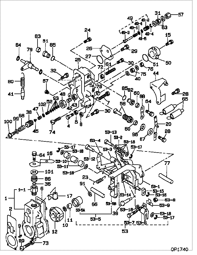
| 000. | [01] | 19080-00730 | GOVERNOR ASSY, MEC | 22310-4460 |
| 001. | [01] | 09081-00222 | HOUSING SUB-ASSY, | 22390-1180A |
| 001-001. | [01] | 09101-60020 | BUSHING, BEARING | 22322-1180A |
| 002. | [01] | 09011-90040 | GASKET, PUMP BODY | 22352-1180A |
| 002. | [01] | 09011-90160 | GASKET, PUMP BODY | 22847-2510A |
| 004. | [01] | 09082-10254 | STOPPER | 22865-1320A |
| 005. | [01] | 09116-90024 | NUT | 22825-1890A |
| 006. | [01] | 09082-30400 | GASKET | 22847-2390A |
| 006. | [01] | 09082-30141 | GASKET | 22847-1800A |
| 007. | [01] | 09128-40080 | SCREW, ADJUSTING | 22395-1470A |
| 008. | [01] | 90160-06051 | NUT, HEXAGON | 22825-1480A |
| 009. | [01] | 94913-00050 | KEY, WOODRUFF | 22891-1040A |
| 010. | [01] | 94901-50500 | WASHER, SPRING | 22877-1540A |
| 011. | [01] | 09084-40010 | NUT, ROUND | 22353-1070A |
| 012. | [01] | 09084-00480 | FLYWEIGHT ASSY | 22360-1200A |
| 015. | [01] | 94904-71770 | BOLT, W/WASHER | 22815-1450A |
| 016. | [01] | 09109-81870 | STOPPER | 22348-1800A |
| 017. | [01] | 09115-90110 | ARM SUB-ASSY | 22348-1700A |
| 020. | [01] | 09107-02140 | LEVER SUB-ASSY, AD | 22309-2760A |
| 023. | [01] | 09099-30140 | SPRING, START | 22331-1130A |
| 024. | [01] | 94904-72220 | BOLT, W/WASHER | 22815-2590A |
| 025. | [01] | 09101-11591 | COVER, GOVERNOR | 22302-1270A |
| 026. | [01] | 09105-10200 | PLATE, COVER | 22386-1240A |
| 027. | [01] | 94914-02030 | O-RING | 22817-1310A |
| 028. | [03] | 91418-06201 | BOLT, W/WASHER | 22815-1290A |
| 029. | [02] | 94904-71790 | BOLT, W/WASHER | 22815-1430A |
| 030. | [03] | 94904-71740 | BOLT, W/WASHER | 22815-1460A |
| 031. | [01] | 94805-30090 | NUT, HEXAGON, W/HO | 22825-1270A |
| 032. | [02] | 94904-71780 | BOLT, W/WASHER | 22815-1470A |
| 036. | [01] | 94914-00130 | O-RING | 22817-1440A |
| 038. | [01] | 09091-10200 | SCREW, ADPTER | 22375-1030A |
| 039. | [01] | 09091-90380 | ADAPTER | 22385-1550A |
| 040. | [02] | 09025-10010 | WASHER, INJECTION | 22865-1290A |
| 041. | [01] | 09133-70050 | DAMPER, FLYWEIGHT | 22385-1060A |
| 042. | [01] | 09091-10231 | SCREW, ADPTER | 22375-1050A |
| 043. | [01] | 09092-30011 | NUT, ADAPTER LOCK | 22825-2090A |
| 044. | [01] | 09097-50800 | ARM, SPRING | 22343-2710A |
| 045. | [01] | 09091-70070 | SEAT, SPRING | 22351-1030A |
| 047. | [01] | 09091-81680 | SPRING, MECHANICAL | 22411-1750 |
| 048. | [01] | 09092-30050 | NUT, ADAPTER LOCK | 22825-1030A |
| 049. | [01] | 09091-00421 | ADAPTER ASSY | 22404-1480A |
| 049-001. | [01] | 09091-80441 | SPRING, MECHANICAL | 22411-1550 |
| 049-002. | [01] | 09091-10061 | SCREW, ADPTER | 22385-1370 |
| 049-003. | [01] | 09091-90170 | ADAPTER | 6 306 1341 80 |
| 049-004. | [01] | 09089-40010 | E-RING | 22863-1810A |
| 049-005. | [01] | 90208-05000 | WASHER, PLATE | |
| 049-006. | [1C] | 94901-33910 | WASHER, PLATE, SK | 6 303 1301 80 |
| 049-006. | [1C] | 94901-33920 | WASHER, PLATE, SK | 6 306 1319 00 |
| 050. | [01] | 09105-10320 | PLATE, COVER | 22351-1010A |
| 051. | [01] | 94914-01900 | O-RING | 22817-1550A |
| 052. | [01] | 09091-81040 | SPRING, MECHANICAL | 22411-1060A |
| 053. | [01] | 09092-90120 | ASSY DRAWING, CONT | |
| 053-001. | [01] | 09092-00270 | LEVER KIT, CONTROL | 22407-1090A |
| 053-002. | [01] | 09143-60220 | LEVER SUB-ASSY, FL | 22350-1200A |
| 053-003. | [01] | 09093-00180 | LEVER ASSY, CONTRO | 22041-1050A |
| 053-004. | [01] | 09093-00340 | LEVER ASSY, CONTRO | |
| 053-005. | [01] | 09084-30030 | ASSY DRAWING, SLEE | |
| 053-006. | [01] | 09094-00111 | LEVER SUB-ASSY, CO | 22042-1320A |
| 053-007. | [01] | 09152-40190 | SCREW, STOPPER | 22395-1090A |
| 053-008. | [01] | 90177-06361 | NUT, HEXAGON | 22825-1220A |
| 053-009. | [01] | 09140-30100 | WASHER, LOCK | 22877-1210A |
| 053-010. | [01] | 09104-90260 | COLLAR | 22332-1150A |
| 053-010. | [01] | 09104-90350 | COLLAR | 22322-1820A |
| 053-011. | [02] | 09104-90340 | COLLAR | 22877-1730A |
| 053-012. | [01] | 09098-30370 | PIN, CONNECTING | 22455-1280A |
| 053-013. | [01] | 09098-30191 | PIN, CONNECTING | 22455-1040A |
| 053-014. | [01] | 09104-20740 | SPRING, RETURN | 22341-2030A |
| 053-015. | [01] | 09094-40120 | BUSHING | 22322-1600A |
| 053-016. | [01] | 09089-40070 | E-RING | 22456-1130A |
| 053-017. | [04] | 90577-05000 | E-RING | 22887-1170A |
| 053-018. | [8C] | 94901-33950 | WASHER, PLATE, SK | 22855-1020A |
| 053-018. | [8C] | 94901-33960 | WASHER, PLATE, SK | 22885-1030A |
| 053-05A. | [01] | 09086-00230 | SLEEVE SUB-ASSY, F | 22305-1160A |
| 053-05B. | [01] | 09095-90200 | LEVER ASSY, GUIDE | 22307-1110A |
| 057. | [01] | 09003-20040 | CAP | 22342-1110A |
| 058. | [01] | 09102-60040 | SHAFT & BUSHING KI | 22322-1890A |
| 060. | [02] | 94915-01150 | SEAL, OIL | 22827-1150A |
| 061. | [01] | 09082-10010 | STOPPER | 22395-1290A |
| 063. | [02] | 94901-80350 | WASHER, COPPER PLA | 22847-1950A |
| 064. | [02] | 91418-06141 | BOLT, W/WASHER | 22815-1480A |
| 065. | [02] | 09104-10110 | SPRING SUB-ASSY, R | 22341-1720A |
| 066. | [01] | 09098-90051 | SHAFT, LEVER SUPPO | 22338-1160A |
| 067. | [01] | 09099-10010 | PLUG, SCREW | 22845-1210A |
| 068. | [01] | 09091-81230 | SPRING, MECHANICAL | 22414-1050A |
| 072. | [01] | 94905-30140 | NUT, HEXAGON, W/ H | 22825-1250A |
| 073. | [01] | 09116-90034 | NUT | 22825-1950A |
| 074. | [01] | 09100-60180 | SCREW, STROKE ADJU | 22396-1220A |
| 075. | [01] | 09092-30070 | NUT, ADAPTER LOCK | 22825-1390A |
| 076. | [01] | 09003-20080 | CAP | 22342-1180A |
| 077. | [01] | 09103-50183 | SHAFT, MECHANICAL | 22318-1020A |
| 078. | [02] | 09101-60221 | BUSHING, BEARING | 22845-1370A |
| 079. | [01] | 09104-80110 | LEVER SUB-ASSY, SU | 22306-1050A |
| 080. | [01] | 09099-20670 | SPRING, SPEED CONT | 22321-1980A |
| 081. | [01] | 09089-20011 | BUSHING, LEVER | 22322-1440A |
| 082. | [01] | 09089-20040 | BUSHING, LEVER | 22322-1590A |
| 083. | [01] | 09109-40010 | CAP, LEVER | 22855-1060A |
| 084. | [02] | 94907-10090 | WASHER, SNAP | 22887-1050A |
| 085. | [02] | 94914-00080 | O-RING | 22817-1190A |
| 086. | [01] | 09104-20690 | SPRING, RETURN | 22341-1750A |
| 087. | [01] | 09154-60010 | SHIM | 22885-1800A |
| 088. | [01] | 09107-10941 | LEVER, ADJUSTING | 22415-1400A |
| 089. | [01] | 09082-10291 | STOPPER | 22865-1370A |
| 091. | [1C] | 94901-34100 | WASHER, PLATE, SK | 22885-5160A |
| 091. | [1C] | 94901-34090 | WASHER, PLATE, SK | 22885-5150A |
| 091. | [1C] | 94901-34080 | WASHER, PLATE, SK | 22885-5140A |
| 091. | [1C] | 94901-34070 | WASHER, PLATE, SK | 22885-5130A |
| 091. | [1C] | 94901-34060 | WASHER, PLATE, SK | 22885-5120A |
| 093. | [05] | 94901-35550 | WASHER, PLATE, SK | 22885-1490A |
| 096. | [1C] | 09154-60080 | SHIM | 22885-1700A |
| 096. | [1C] | 09154-60050 | SHIM | 22885-5110A |
| 096. | [1C] | 09154-60040 | SHIM | 22885-5100A |
| 096. | [1C] | 09154-60030 | SHIM | 22885-5090A |
| 099. | [1C] | 09091-70210 | SEAT, SPRING | 22885-5080A |
| 099. | [1C] | 09091-70200 | SEAT, SPRING | 22885-5070A |
| 099. | [1C] | 09091-70190 | SEAT, SPRING | 22885-5060A |
| 099. | [1C] | 09091-70180 | SEAT, SPRING | 22885-5050A |
| 099. | [1C] | 09091-70170 | SEAT, SPRING | 22885-5040A |
| 099. | [1C] | 09091-70160 | SEAT, SPRING | 22885-5030A |
| 099. | [1C] | 09091-70150 | SEAT, SPRING | 22885-5020A |
| 099. | [1C] | 09091-70140 | SEAT, SPRING | 22885-5010A |
| 099. | [1C] | 09091-70130 | SEAT, SPRING | 22885-5000A |
| 099. | [1C] | 09091-70120 | SEAT, SPRING | 22885-4990A |
| 099. | [1C] | 09091-70110 | SEAT, SPRING | 22885-4980A |
| 099. | [1C] | 09091-70100 | SEAT, SPRING | 22885-4970A |
| 099. | [1C] | 09091-70090 | SEAT, SPRING | 22885-4960A |
| 100. | [01] | 09104-90270 | COLLAR | 22351-1620A |
| 101. | [1C] | 94901-31960 | WASHER, PLATE, SK | 22885-3430A |
| 101. | [1C] | 94901-31970 | WASHER, PLATE, SK | 22885-3440A |
| 101. | [1C] | 94901-32220 | WASHER, PLATE, SK | 22885-5220A |
| 102. | [1C] | 94901-31360 | WASHER, PLATE, SK | 22885-1200A |
| 102. | [1C] | 94901-35040 | WASHER, PLATE, SK | 22885-1210A |
Include in #3:
Cross reference number
| Part num | Firm num | Firm | Name |
| 19080-00730 | 22310-4460 | GOVERNOR ASSY, MEC | |
| 22310-4460A | HINO | GOVERNOR ASSY, MEC | |
| 22310-4460 | HINO | GOVERNOR ASSY, MEC |
Information:
1. Remove bolts (1) that hold plate (2), and remove the plate. 2. Remove bolts (3) and (4) that hold the cylinder head assembly to the cylinder block.3. Fasten a hoist, and remove the cylinder head assembly. The weight is approximately 135 kg (300 lb.).
Do not put the cylinder head assembly down on a flat surface. This can cause damage to the fuel injection valves.
4. Remove the gasket, seals (5) and O-ring seals (6) from the spacer plate. The following steps are for installation of the cylinder head. Be sure a new gasket has been installed between the spacer plate and the cylinder block. See the topic, Remove And Install Spacer Plate.5. Thoroughly clean the spacer plate and the bottom surface of the cylinder head assembly. Install a new head gasket, new seals (5) and two O-ring seals (6).6. Fasten a hoist, and put the cylinder head assembly in position on the cylinder block. 7. Put clean engine oil on the threads of the cylinder head bolts. Install the cylinder head bolts and washers. Tighten the bolts in sequence shown.a. Tighten bolts 1 through 20 in number sequence to a torque of 270 25 N m (200 18 lb.ft.).b. Tighten bolts 1 through 20 in number sequence to a torque of 450 20 N m (330 15 lb.ft.).c. Tighten bolts 1 through 20 in number sequence to a torque of 450 20 N m (330 15 lb.ft.) by hand.d. Install the rocker shaft assemblies and push rods. See the topic, Install Rocker Shaft Assemblies And Push Rods.e. Tighten bolts 21 through 26 in number sequence to a torque of 270 25 N m (200 18 lb.ft.).f. Tighten bolts 21 through 26 in number sequence to a torque of 450 20 N m (330 15 lb.ft.).g. Tighten bolts 21 through 26 in number sequence to a torque of 450 20 N m (330 15 lb.ft.) by hand.h. Tighten the 3/8" bolts (5) to a torque of 43 7 N m (32 5 lb.ft.). If the studs for the exhaust manifold were removed, install new studs, and tighten them to a torque of 25 4 N m (18 3 lb.ft.).8. Make an adjustment to the valves to have a clearance of 0.38 mm (.015 in.) for intake and 0.76 mm (.030 in.) for exhaust. Tighten the locknuts for the valve adjustment screws to a torque of 28 4 N m (21 3 lb.ft.).9. Install the valve cover bases and the inner fuel lines. See the topic, Install Rocker Shaft Assemblies And Push Rods.10. Install the valve covers. See Install Valve Covers.11. Install plate (2).End By:a. install aftercooler housingb. install exhaust manifoldc. install fuel injection linesd. install water temperature regulator