Information body assy, injecti
Rating:
KIT List:
| Body assy, injecti | No Application |
| Body assy, injecti | No Application |
| Body assy, injecti | No Application |
| Body assy, injecti | No Application |
| Body assy, injecti | No Application |
Scheme ###:
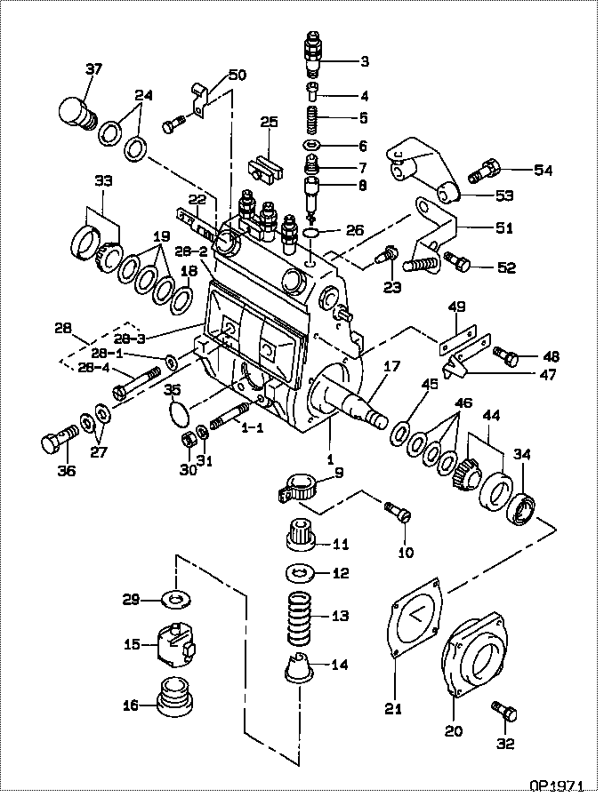
| 000. | [01] | 19010-00820 | BODY ASSY, INJECTI | 22110-3160 |
| 000. | [01] | 19010-00820 | BODY ASSY, INJECTI | S2211-03160 |
| 001. | [01] | 19011-05220 | HOUSING KIT, INJEC | |
| 001-001. | [03] | 94904-30010 | BOLT, STUD | 22857-1060A |
| 001-002. | [01] | 09022-10070 | UNION, INJECTION P | 22131-1050A |
| 001-003. | [01] | 09022-10090 | UNION, INJECTION P | |
| 001-003. | [01] | 09022-10040 | UNION, INJECTION P | |
| 003. | [04] | 09013-11101 | HOLDER, DELIVERY V | 22116-1200A |
| 004. | [04] | 09013-30390 | STOPPER, DELIVERY | 22117-1310A |
| 005. | [04] | 09013-61211 | SPRING, DELIVERY V | 22125-1410A |
| 006. | [04] | 09013-70160 | GASKET, DELIVERY V | 22847-2500A |
| 007. | [04] | 09014-02561 | VALVE SUB-ASSY, IN | 22103-2380A |
| 008. | [04] | 09015-05561 | ELEMENT SUB-ASSY, | 22104-3501A |
| 009. | [04] | 09015-60010 | PINION, PLUNGER CO | 22128-1020A |
| 010. | [04] | 09015-70010 | SCREW, PLUNGER CON | 22865-1280A |
| 011. | [04] | 09016-10500 | SLEEVE, PLUNGER CO | 22118-1280A |
| 012. | [04] | 09016-30191 | SEAT, SPRING, UPR | 22119-1190A |
| 013. | [04] | 09016-40350 | SPRING, PUMP PLUNG | 22121-1430A |
| 014. | [04] | 09016-50320 | SEAT, SPRING, LWR | 22122-1170A |
| 015. | [04] | 09017-00350 | TAPPET SUB-ASSY,IN | 22105-1560A |
| 016. | [04] | 09018-90080 | PLUG, INJECTION PU | 22845-1470A |
| 017. | [01] | 09019-11660 | CAMSHAFT, INJECTIO | |
| 018. | [01] | 09019-30020 | RING, CAMSHAFT ADJ | 22124-1160A |
| 019. | [3C] | 09019-40400 | PLATE, CAMSHAFT SH | 22885-6660A |
| 019. | [3C] | 09019-40290 | PLATE, CAMSHAFT SH | 22885-5840A |
| 019. | [3C] | 09019-40150 | PLATE, CAMSHAFT SH | 22129-1200A |
| 019. | [3C] | 09019-40140 | PLATE, CAMSHAFT SH | 22129-1190A |
| 019. | [3C] | 09019-40110 | PLATE, CAMSHAFT SH | 22885-5830A |
| 019. | [3C] | 09019-40060 | PLATE, CAMSHAFT SH | 22885-4950A |
| 019. | [3C] | 09019-40050 | PLATE, CAMSHAFT SH | 22885-4940A |
| 019. | [3C] | 09019-40040 | PLATE, CAMSHAFT SH | 22885-4930A |
| 019. | [3C] | 09019-40030 | PLATE, CAMSHAFT SH | 22885-4920A |
| 019. | [3C] | 09019-40020 | PLATE, CAMSHAFT SH | 22885-4910A |
| 019. | [3C] | 09019-40010 | PLATE, CAMSHAFT SH | 22885-4900A |
| 020. | [01] | 09020-10250 | COVER, BEARING | 22111-1540A |
| 020. | [01] | 09020-10820 | COVER, BEARING | 22111-1810A |
| 021. | [01] | 09020-60200 | GASKET, BEARING CO | 22847-2230A |
| 022. | [01] | 09021-20760 | RACK, CONTROL | 22113-1500A |
| 023. | [01] | 09021-50060 | SCREW, RACK GUIDE | 22811-4850A |
| 024. | [02] | 94901-02490 | WASHER | 22877-1100A |
| 025. | [02] | 09023-00050 | PLATE SET, VALVE H | 22109-1170A |
| 026. | [04] | 94914-02570 | O-RING | 22817-1260A |
| 027. | [02] | 94901-02470 | WASHER | 22847-1900A |
| 028. | [01] | 09027-01460 | COVER SUB-ASSY, IN | |
| 028-001. | [02] | 09024-30030 | PACKING, AIR BLEED | 22847-1890A |
| 028-002. | [01] | 09027-20210 | GASKET, INJECTION | 22847-1990A |
| 028-003. | [01] | 09027-50182 | PROCESSING DRAWING | 22127-1210A |
| 028-004. | [02] | 09027-60030 | SCREW | 22815-1550A |
| 029. | [4C] | 09031-10290 | PLATE, TAPPET ADJU | 22885-2270A |
| 029. | [4C] | 09031-10150 | PLATE, TAPPET ADJU | 22885-1250A |
| 029. | [4C] | 09031-10140 | PLATE, TAPPET ADJU | 22885-1370A |
| 029. | [4C] | 09031-10130 | PLATE, TAPPET ADJU | 22885-1360A |
| 029. | [4C] | 09031-10120 | PLATE, TAPPET ADJU | 22885-1350A |
| 029. | [4C] | 09031-10110 | PLATE, TAPPET ADJU | 22885-1240A |
| 029. | [4C] | 09031-10100 | PLATE, TAPPET ADJU | 22885-1230A |
| 029. | [4C] | 09031-10090 | PLATE, TAPPET ADJU | 22885-1340A |
| 029. | [4C] | 09031-10080 | PLATE, TAPPET ADJU | 22885-1330A |
| 029. | [4C] | 09031-10010 | PLATE, TAPPET ADJU | 22885-1130A |
| 029. | [4C] | 09031-10020 | PLATE, TAPPET ADJU | 22885-1140A |
| 029. | [4C] | 09031-10030 | PLATE, TAPPET ADJU | 22885-1150A |
| 029. | [4C] | 09031-10040 | PLATE, TAPPET ADJU | 22885-1160A |
| 029. | [4C] | 09031-10050 | PLATE, TAPPET ADJU | 22885-1170A |
| 029. | [4C] | 09031-10060 | PLATE, TAPPET ADJU | 22885-1180A |
| 029. | [4C] | 09031-10070 | PLATE, TAPPET ADJU | 22885-1190A |
| 030. | [03] | 90160-06051 | NUT, HEXAGON | 22825-1480A |
| 031. | [03] | 90258-06001 | WASHER, SPRING | 28219-1110A |
| 032. | [04] | 94904-71360 | BOLT, W/WASHER | 22815-2500A |
| 033. | [01] | 94910-10120 | BEARING, ROLLER | 22837-1230A |
| 034. | [01] | 94915-01620 | SEAL, OIL | 22827-1040A |
| 035. | [01] | 94914-00380 | O-RING | 22817-1540A |
| 036. | [01] | 94918-00060 | SCREW, HOLLOW | 22835-1110A |
| 037. | [01] | 94918-00310 | SCREW, HOLLOW | S2283-51310-A |
| 044. | [01] | 94910-10071 | BEARING, ROLLER | 22837-1100A |
| 045. | [01] | 09019-30050 | RING, CAMSHAFT ADJ | 22124-1090A |
| 046. | [3C] | 09019-40410 | PLATE, CAMSHAFT SH | 22885-6670A |
| 046. | [3C] | 09019-40360 | PLATE, CAMSHAFT SH | 22885-5700A |
| 046. | [3C] | 09019-40350 | PLATE, CAMSHAFT SH | 22885-5690A |
| 046. | [3C] | 09019-40340 | PLATE, CAMSHAFT SH | 22885-5680A |
| 046. | [3C] | 09019-40170 | PLATE, CAMSHAFT SH | 22129-1180A |
| 046. | [3C] | 09019-40160 | PLATE, CAMSHAFT SH | 22129-1170A |
| 046. | [3C] | 09019-40100 | PLATE, CAMSHAFT SH | 22885-1580A |
| 046. | [3C] | 09019-40090 | PLATE, CAMSHAFT SH | 22885-1570A |
| 046. | [3C] | 09019-40080 | PLATE, CAMSHAFT SH | 22885-1560A |
| 046. | [3C] | 09019-40070 | PLATE, CAMSHAFT SH | 22885-1550A |
| 047. | [01] | 09011-80560 | NEEDLE, TIMING | |
| 048. | [02] | 91418-06121 | BOLT, W/WASHER | 22815-1500A |
| 049. | [01] | 09020-80290 | PLATE, SHIM | 22885-5860A |
| 050. | [01] | 09039-10090 | CLIP, CORD | |
| 051. | [01] | 09069-00850 | BRACKET SUB-ASSY, | |
| 052. | [01] | 91418-08161 | BOLT, W/WASHER | |
| 053. | [01] | 09045-30120 | STAY, INJECTION PU | 11409-1130A |
| 054. | [02] | 91418-08351 | BOLT, W/WASHER | 9161B-60835 |
Include in #3:
Cross reference number
| Part num | Firm num | Firm | Name |
| 19010-00820 | BODY ASSY, INJECTI | ||
| 22110-3160 | HINO | BODY ASSY, INJECTI | |
| S2211-03160 | HINO | BODY ASSY, INJECTI |
Information:
Fig. 1-Engine Balancer ShaftsTwo types of balancer shafts are used (Fig. 1). They are mounted in the lower half of the cylinder block and each rotates in three pressure-lubricated replaceable bushings.The balancer shafts rotate in opposite directions to reduce engine vibration. Thrust of the balancer shafts is absorbed by thrust plates fastened to the front of the cylinder block.Removal
Remove fan belts, alternator, and fan.Remove oil pan.Disconnect oil cooler lines.Use a pulley puller to remove the crankshaft pulley.Remove the timing gear cover.Remove weights (2, Fig. 1), from the balancer shafts, if equipped.Remove oil pump gear and lower idler gear.Remove balancer shafts and identify as left and right.Remove balancer shaft gears (4, Fig. 1) by pressing them off.Remove balancer shaft thrust plates (3, Fig. 1).Repair
Fig. 2-Balancer Shaft Journals and Bushings MeasurementCheck oil clearance between balancer shaft journals (2, Fig. 2) and bushings (1). Maximum allowable clearance is 0.0058 in. (0.147 mm). If clearance is greater than this replace the bushings. If oil clearance is still too large, the balancer shaft must be replaced.
Fig. 3-Bushing RemovalThe first two bushings can be replaced using JD-249 Tool, Fig. 3.To remove the third bushing the flywheel housing must be removed, see Group 0433. IMPORTANT: Be sure that hole in each bushing lines up with upper oil lead hole in cylinder block.Press all bushings in from the front of the engine until flush with bushing bore chamfer in block using JD249 Tool.Inspect balancer shaft gears for worn, cracked or broken teeth.Installing Drive Gear
It may be necessary to place thrust plate on the shaft before installing the gear on the shaft depending on the type of thrust plate used.
Fig. 4-Replacing Balancer Shaft GearPosition balancer shaft drive gear on front of balancer shaft so slot in gear lines up with special key, and timing mark on front of gear faces away from balancer shaft. Press on gear using JD-247 Holding Tool to support shaft as shown in Fig. 4. Press gear on shaft with thrust plate in position. Clearance between thrust plate and gear should be 0.002 to 0.010 in. (0.05 to 0.25 mm).Installation
Apply a light film of oil to balancer journals and bushings.Secure thrust plates to front plate with hardware and tighten with 35 lb-ft (47 Nm) (5 kg-m).
Fig. 5-Timing Balancer ShaftInstall balancer shafts in their respective bores. Time balancer shafts as shown in Fig. 5 using JD254 Timing Tool.With a dial indicator check balancer shaft for end play of no more than 0.010 in. (0.25 mm) or no less than 0.002 in. (0.05 mm).
Fig. 6-Installing Balancer Shaft WeightsInstall balancer shaft weights, if used, being sure weights are installed on the machine surfaces of the shaft. Run the balancer shaft bolts through the weights and then through the shafts as shown in Fig. 6. Tighten special nuts to 43 lb-ft (58 N m) (6 kg-m).Replace oil pump gear and lower idler gear if necessary.
Fig. 7-Installing Timing Gear CoverInstall timing gear cover and crankshaft pulley (Fig. 7).Install engine oil cooler coolant hose.Install fan, alternator and fan belts.Adjust