Information body assy, injecti
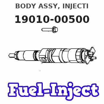
BODY ASSY, INJECTI
EB
- * THE ELEMENT(NO.8)IS DIFFERNT, COMPARING WITH
- 190100-1110.
Rating:
KIT List:
| Body assy, injecti | 1904400360 |
| Body assy, injecti | 1904400360 |
| Body assy, injecti | 1904400360 |
| Body assy, injecti | 1904400360 |
| Body assy, injecti | 1904400360 |
| Body assy, injecti | 1904400360 |
| Body assy, injecti | 1904400360 |
| Body assy, injecti | 1904400360 |
| Body assy, injecti | 1904400360 |
Scheme ###:
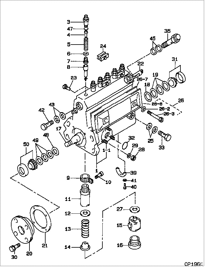
| 000. | [01] | 19010-00500 | BODY ASSY, INJECTI | |
| 001. | [01] | 19011-05200 | HOUSING KIT, INJEC | |
| 001-001. | [03] | 94904-30010 | BOLT, STUD | 85265-00057 |
| 001-002. | [01] | 09022-10070 | UNION, INJECTION P | |
| 001-003. | [01] | 09022-10310 | UNION, INJECTION P | |
| 001-003. | [01] | 09022-10010 | UNION, INJECTION P | |
| 003. | [06] | 09013-10710 | HOLDER, DELIVERY V | |
| 004. | [06] | 09013-30261 | STOPPER, DELIVERY | |
| 005. | [06] | 09013-61190 | SPRING, DELIVERY V | |
| 006. | [06] | 09013-70100 | GASKET, DELIVERY V | 09013-70100 |
| 007. | [06] | 09014-01890 | VALVE SUB-ASSY, IN | |
| 008. | [06] | 09015-03050 | ELEMENT SUB-ASSY, | |
| 009. | [06] | 09015-60010 | PINION, PLUNGER CO | 85265-00074 |
| 010. | [06] | 09015-70010 | SCREW, PLUNGER CON | 85265-00027 |
| 011. | [06] | 09016-10330 | SLEEVE, PLUNGER CO | |
| 012. | [06] | 09016-30191 | SEAT, SPRING, UPR | |
| 013. | [06] | 09016-40350 | SPRING, PUMP PLUNG | |
| 014. | [06] | 09016-50160 | SEAT, SPRING, LWR | 09016-50160 |
| 015. | [06] | 09017-00070 | TAPPET SUB-ASSY,IN | 09017-00070 |
| 016. | [06] | 09018-90090 | PLUG, INJECTION PU | 09018-90090 |
| 017. | [01] | 09019-10960 | CAMSHAFT, INJECTIO | |
| 018. | [01] | 09019-30020 | RING, CAMSHAFT ADJ | 09019-30020 |
| 019. | [3C] | 09019-40010 | PLATE, CAMSHAFT SH | 09019-40010 |
| 019. | [3C] | 09019-40400 | PLATE, CAMSHAFT SH | |
| 019. | [3C] | 09019-40290 | PLATE, CAMSHAFT SH | |
| 019. | [3C] | 09019-40150 | PLATE, CAMSHAFT SH | |
| 019. | [3C] | 09019-40140 | PLATE, CAMSHAFT SH | |
| 019. | [3C] | 09019-40110 | PLATE, CAMSHAFT SH | 09019-40110 |
| 019. | [3C] | 09019-40060 | PLATE, CAMSHAFT SH | 09019-40060 |
| 019. | [3C] | 09019-40050 | PLATE, CAMSHAFT SH | 09019-40050 |
| 019. | [3C] | 09019-40040 | PLATE, CAMSHAFT SH | 09019-40040 |
| 019. | [3C] | 09019-40030 | PLATE, CAMSHAFT SH | 09019-40030 |
| 019. | [3C] | 09019-40020 | PLATE, CAMSHAFT SH | 09019-40020 |
| 020. | [01] | 09020-10351 | COVER, BEARING | 09020-10351 |
| 021. | [01] | 09020-60150 | GASKET, BEARING CO | |
| 022. | [01] | 09021-20010 | RACK, CONTROL | 85265-00023 |
| 023. | [01] | 09021-50060 | SCREW, RACK GUIDE | 09021-50060 |
| 024. | [03] | 09023-00050 | PLATE SET, VALVE H | 09023-00050 |
| 025. | [02] | 09025-10010 | WASHER, INJECTION | 85265-00077 |
| 026. | [01] | 09027-00691 | COVER SUB-ASSY, IN | |
| 026. | [01] | 09027-00622 | COVER SUB-ASSY, IN | |
| 026-002. | [02] | 09024-30030 | PACKING, AIR BLEED | 85265-00016 |
| 026-003. | [02] | 09027-60030 | SCREW | |
| 026-006. | [01] | 09027-50083 | PROCESSING DRAWING | |
| 026-007. | [01] | 09027-20220 | GASKET, INJECTION | |
| 027. | [6C] | 09031-10290 | PLATE, TAPPET ADJU | |
| 027. | [6C] | 09031-10150 | PLATE, TAPPET ADJU | 09031-10150 |
| 027. | [6C] | 09031-10140 | PLATE, TAPPET ADJU | 09031-10140 |
| 027. | [6C] | 09031-10130 | PLATE, TAPPET ADJU | 09031-10130 |
| 027. | [6C] | 09031-10120 | PLATE, TAPPET ADJU | 09031-10120 |
| 027. | [6C] | 09031-10110 | PLATE, TAPPET ADJU | 09031-10110 |
| 027. | [6C] | 09031-10100 | PLATE, TAPPET ADJU | 09031-10100 |
| 027. | [6C] | 09031-10090 | PLATE, TAPPET ADJU | 09031-10090 |
| 027. | [6C] | 09031-10080 | PLATE, TAPPET ADJU | 09031-10080 |
| 027. | [6C] | 09031-10010 | PLATE, TAPPET ADJU | 09031-10010 |
| 027. | [6C] | 09031-10020 | PLATE, TAPPET ADJU | 09031-10020 |
| 027. | [6C] | 09031-10030 | PLATE, TAPPET ADJU | 09031-10030 |
| 027. | [6C] | 09031-10040 | PLATE, TAPPET ADJU | 09031-10040 |
| 027. | [6C] | 09031-10050 | PLATE, TAPPET ADJU | 09031-10050 |
| 027. | [6C] | 09031-10060 | PLATE, TAPPET ADJU | 09031-10060 |
| 027. | [6C] | 09031-10070 | PLATE, TAPPET ADJU | 09031-10070 |
| 028. | [03] | 90160-06051 | NUT, HEXAGON | 85265-00085 |
| 029. | [03] | 90258-06001 | WASHER, SPRING | 90258-06001 |
| 030. | [04] | 91418-06201 | BOLT, W/WASHER | 91418-06201 |
| 031. | [01] | 94910-10120 | BEARING, ROLLER | 94910-10121 |
| 032. | [01] | 94914-00380 | O-RING | 85265-00084 |
| 033. | [01] | 94918-00060 | SCREW, HOLLOW | 85265-00076 |
| 035. | [01] | 09031-00130 | VALVE ASSY, OVERFL | |
| 039. | [01] | 09036-10150 | BEARING, CENTER | |
| 040. | [02] | 94900-66550 | SCREW | |
| 041. | [02] | 94901-81030 | WASHER, COPPER PLA | 85265-00068 |
| 042. | [01] | 94918-00310 | SCREW, HOLLOW | 85265-00078 |
| 043. | [02] | 09022-20070 | WASHER, FUEL PIPE | 85265-00079 |
| 045. | [02] | 09022-20060 | WASHER, FUEL PIPE | 09022-20060 |
| 047. | [06] | 94914-02570 | O-RING | 94914-02570 |
| 048. | [01] | 09019-30050 | RING, CAMSHAFT ADJ | |
| 049. | [3C] | 09019-40410 | PLATE, CAMSHAFT SH | |
| 049. | [3C] | 09019-40360 | PLATE, CAMSHAFT SH | |
| 049. | [3C] | 09019-40350 | PLATE, CAMSHAFT SH | |
| 049. | [3C] | 09019-40340 | PLATE, CAMSHAFT SH | |
| 049. | [3C] | 09019-40170 | PLATE, CAMSHAFT SH | |
| 049. | [3C] | 09019-40160 | PLATE, CAMSHAFT SH | |
| 049. | [3C] | 09019-40100 | PLATE, CAMSHAFT SH | 09019-40100 |
| 049. | [3C] | 09019-40090 | PLATE, CAMSHAFT SH | 09019-40090 |
| 049. | [3C] | 09019-40080 | PLATE, CAMSHAFT SH | 09019-40080 |
| 049. | [3C] | 09019-40070 | PLATE, CAMSHAFT SH | 09019-40070 |
| 050. | [01] | 94910-10071 | BEARING, ROLLER |
Include in #3:
09200-00870
as BODY ASSY, INJECTI
19010-00500
Cross reference number
| Part num | Firm num | Firm | Name |
| 19010-00500 | BODY ASSY, INJECTI |
Information:
Secure engine in swivelling mounting stand.1. Dismantle the following units and components: Air filter with holder, starter, air compressor with bracket and lubricating oil line, generator with holder, fuel-supply line to the flame-type heater plug or the pipe connecting with the pilot injector, induction manifold, exhaust manifold, cover plate on the exit air side, air cowling, fuel and lubricating oil filters with their supply lines, leak-off and delivery lines, vertical plate on the fly-wheel side, blower, front vertical plate, oil cooler, air cowling, vee-belt idler.
9-13 Immediately fuel line unions are dismantled plug or fit caps on the connecting stubs and pipe ends.Fig. 9-13
9-142. Dismantle the vee-belt pulley for the air compressor, main belt pulley and front cover. (Use retainer for vee-belt pulley, No. 143400).Fig. 9-14 The screw securing the vee-belt pulley has a left-hand thread.
9-153. Disassemble the nut on the fuel-injection pump's driving shaft. (Use the universal device No. 110340 or a 19 mm socket spanner).Fig. 9-15 Important:As from 1975, the hub was modified in the case of rigid drive. (The thread for attachment of tool No. 110340 with sleeve has been omitted). Remove gear-wheel fastening screws. (See Section 7)
9-164. Mount the tool without sleeve if the pump drive has on injection timer. If it has no injection timer mount the tool with sleeve (Universal device No. 110340).Fig. 9-16
9-175. Pull the injection pump drive from the pump shaft. Dismantle the pump and the securing flange.Fig. 9-17
9-186. Dismantle the injectors, upper cover plate, valve covers and rocker arm shaft brackets, remove the push-rods and unscrew the plugs. (Use socket spanner No. 120040, square socket insert No. 120060)Fig. 9-18, left7. Slacken the cylinder head studs in stages, in diagonal sequence. (Use socket spanner No. 120040)Fig. 9-18, right8. Dismantle the cylinder heads and pushrod sheaths.
9-199. Turn engine upside down. Dismantle the sump with sheet-metal partition, crankcase breather and oil strainer. Disassemble the big-end bearing bolts. (Use bent socket spanner No. 131540)Fig. 9-1910. Slacken and remove the big-end bearing caps. Withdraw the cylinders with pistons and connecting rods from the crankcase. Remove the halves of bearing shells and mark them on the back corresponding to the connecting rods with an electric scriber. Make sure that the bearing shells do not get damaged.11. Dismantle the oil pump and idler gear, camshaft and tappets, flywheel and main bearing caps.12. Remove the crankshaft and the halves of bearing shells. Mark the bearing shells on the back corresponding to the crankcase with an electric scriber. Unscrew the plugs, oil feeders and oil injection nozzles from the crankcase. Clean all parts and thouroughly wash out the oilways.
9-20 Remove horizontal oil nozzles. Fig. 9-2013. Check all parts for suitability for reuse.Assembling The Crankshaft Assembly (as from 3 cylinder engine)
It is assumed that the liner is fitted in the front camshaft bearing bore.
9-611. Place the crankcase with the cylinder head joint face downwards. Screw the dosing plugs in the oilways of