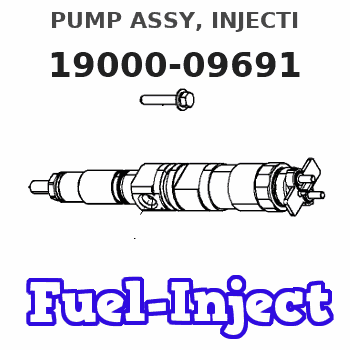
Information pump assy, injecti
Rating:
Components :
| 001. | PUMP ASSY, INJECTI | 19000-09691 |
| 002. | SWITCH KIT, CONTRO | 09009-90280 |
| 003. | BODY ASSY, INJECTI | 09010-05551 |
| 004. | COVER, BEARING | 09020-10110 |
| 005. | GOVERNOR ASSY, MEC | 09130-01040 |
| 005. | GOVERNOR ASSY, MEC | 09130-01040 |
| 006. | PUMP ASSY, FUEL FE | 09210-00950 |
| 007. | PUMP ASSY, FUEL FE | 09210-01900 |
| 008. | COUPLING ASSY | 09250-00401 |
Scheme ###:
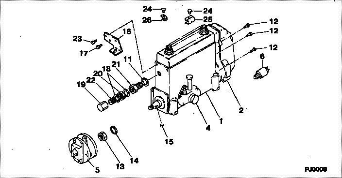
| 000. | [01] | 19000-09691 | PUMP ASSY, INJECTI | 22010-3991 |
| 001. | [01] | 09010-05551 | BODY ASSY, INJECTI | 22110-1140A |
| 002. | [01] | 09130-01040 | GOVERNOR ASSY, MEC | 22310-2931A |
| 002. | [01] | 09130-01041 | GOVERNOR ASSY, MEC | 22310-2931A |
| 004. | [01] | 09210-00950 | PUMP ASSY, FUEL FE | 22570-1260A |
| 004. | [01] | 09210-01900 | PUMP ASSY, FUEL FE | 22570-1330A |
| 005. | [01] | 09250-00401 | COUPLING ASSY | 22610-1330A |
| 006. | [01] | 09009-90280 | SWITCH KIT, CONTRO | 22690-1170A |
| 011. | [01] | 94901-80710 | WASHER, COPPER PLA | 22863-1300A |
| 012. | [08] | 91518-06161 | BOLT, W/WASHER | 22815-1310A |
| 013. | [01] | 94905-03400 | NUT, HEXAGON | 22825-1730A |
| 014. | [01] | 94901-50730 | WASHER, SPRING | 22877-1670A |
| 015. | [01] | 90458-05750 | KEY, WOODRUFF | 22891-1070A |
| 016. | [01] | 09008-80040 | BRACKET ASSY | 22451-1150A |
| 017. | [01] | 91410-08121 | BOLT, W/WASHER | 22815-2300A |
| 018. | [02] | 94901-80350 | WASHER, COPPER PLA | 22847-1950A |
| 019. | [01] | 09003-20040 | CAP | 22342-1110A |
| 020. | [01] | 94805-30100 | NUT, HEXAGON, W/HO | 22885-3830A |
| 021. | [01] | 09001-80152 | COVER, CONTROL RAC | 22372-1100A |
| 022. | [01] | 09002-60050 | SCREW, ADJUSTING | 22396-1140A |
| 023. | [02] | 91410-06141 | BOLT, W/WASHER | 22815-2290A |
| 024. | [02] | 09001-60060 | SEAL, LEAD | 22323-1200A |
| 025. | [01] | 09039-10050 | CLIP, CORD | 22323-1250A |
| 026. | [01] | 09039-10060 | CLIP, CORD | 22323-1240A |
Include in #3:
19000-09691
as PUMP ASSY, INJECTI
Cross reference number
| Part num | Firm num | Firm | Name |
| 19000-09691 | 22010-3991 | PUMP ASSY, INJECTI |
Information:
Remove Governor
Start By:a. remove fuel ratio controlb. remove governor shutoff solenoid 1. Remove the cotter pin and pin (1) that connects the linkage to the lever.2. Remove the bolt, and disconnect clip (3) that holds the fuel line to governor base.3. Disconnect wire assembly (4) from the governor plate.4. Remove the bolts and plate (2) from the governor. 5. Remove bolt (8), stop collar (7) and the spring from the governor. Plate (6) can be removed for easier access to bolt (8). Remove the bolt, cover (5) and bolt (9). 6. Install Tool (A) in the fuel injection pump housing. Move governor control lever (10) until Tool (A) is in place and the racks are in the center (zero) position.7. Remove bolts (11) and governor housing (12). 8. Remove the seat, one flat washer, two spring washers and spring (13).9. Disconnect fuel lines (15) from governor plate (14).10. Remove the bolts and governor plate (14) from the fuel injection pump. It is possible to remove the governor and governor plate as a unit. The above steps must be followed before the governor can be installed again on the injection pump housing.Install Governor
The drive assembly must be removed from the governor plate before the governor plate is installed for correct alignment. The drive assembly can be damaged if it is installed with the governor plate and is not in alignment with the drive pinion assembly.
1. Install a new gasket on the injection pump housing. 2. Make sure Tool (A) holds the racks in the center "zero" position.3. Put governor plate (1) in position on the fuel pump housing. Make sure the dowels in governor plate (1) are in alignment with the holes in the injection pump housing. Install the bolts. 4. Install ring (2) in gear assembly (3). Make sure the dowels in gear assembly (3) are in the center of the slots in ring (2). 5. Install drive assembly (4), the spring and ring (6) in gear assembly (5) as shown. Be sure the dowels in gear assembly (3) and the holes in drive assembly (4) are in alignment.6. Use Tool (B) to install ring (5) in the gear assembly. 7. Install spring (9), the spring washer, the flat washer the spring washer and seat (7).8. Connect fuel lines (8) and wire assembly (10) to the governor plate. 9. Install a new gasket (13) and governor housing (11) on the governor plate with bolts (12).10. Remove Tool (A), and install the plug. 11. Install the spring, stop collar (14) on the governor bolt with bolt (15). 12. Install a new gasket and cover assembly (16) on the governor housing. There is a strainer assembly in the cover assembly. The strainer assembly is installed with the mesh (screen) toward the governor housing. 13. Install new gaskets and plate assembly (17) and cover (19) on the governor housing.14. Connect linkage (18) on the governor lever with the pin and the cotter pin.15. Check the governor adjustment. See the topic "Governor