Information pump assy, injecti
Nozzle:
0935002200
Rating:
KIT List:
| Body assy, injecti | No Application |
| Governor assy, mec | 1908900240 |
| Timer assy, automa | 0918030010 |
| Pump assy, fuel fe | 1922900070 |
Components :
| 001. | PUMP ASSY, INJECTI | 19000-07450 |
| 002. | SWITCH KIT, CONTRO | 09009-90280 |
| 003. | BODY ASSY, INJECTI | 09010-04910 |
| 004. | COVER, BEARING | 09020-10110 |
| 005. | GOVERNOR ASSY, MEC | 09130-00480 |
| 006. | TIMER ASSY, AUTOMA | 09180-01421 |
| 007. | PUMP ASSY, FUEL FE | 09210-01900 |
| 008. | COUPLING ASSY | 09250-00631 |
Scheme ###:
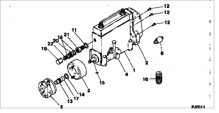
| 000. | [01] | 19000-07450 | PUMP ASSY, INJECTI | 22010-3190 |
| 001. | [01] | 09010-04910 | BODY ASSY, INJECTI | |
| 002. | [01] | 09130-00480 | GOVERNOR ASSY, MEC | 22310-2620A |
| 003. | [01] | 09180-01421 | TIMER ASSY, AUTOMA | 22510-1450 |
| 004. | [01] | 09210-01900 | PUMP ASSY, FUEL FE | 22570-1330A |
| 005. | [01] | 09250-00631 | COUPLING ASSY | 22610-1471A |
| 006. | [01] | 09009-90280 | SWITCH KIT, CONTRO | 22690-1170A |
| 011. | [01] | 94901-80710 | WASHER, COPPER PLA | 22863-1300A |
| 012. | [08] | 91518-06161 | BOLT, W/WASHER | 22815-1310A |
| 013. | [01] | 09001-20230 | NUT, TIMER ROUND | 22825-1110A |
| 014. | [01] | 94901-40070 | WASHER, COUNTERSUN | 22877-1580A |
| 015. | [01] | 90458-05750 | KEY, WOODRUFF | 22891-1070A |
| 016. | [01] | 09006-10030 | COVER, PRIMING PUM | 22561-1040 |
| 017. | [01] | 90801-40280 | O-RING | 22817-1050A |
| 018. | [02] | 94901-80350 | WASHER, COPPER PLA | 22847-1950A |
| 019. | [01] | 09003-20040 | CAP | 22342-1110A |
| 021. | [01] | 09001-80152 | COVER, CONTROL RAC | 22372-1100A |
| 022. | [01] | 09002-60050 | SCREW, ADJUSTING | 22396-1140A |
Include in #3:
19000-07450
as PUMP ASSY, INJECTI
Cross reference number
| Part num | Firm num | Firm | Name |
| 19000-07450 | 22010-3190 | PUMP ASSY, INJECTI | |
| 22010-3190 | HINO | PUMP ASSY, INJECTI |
Information:
1. Loosen the bleed valves and release the air pressure in the air tanks.2. Drain the oil from the oil pan. 3. Remove two short bolts (1) and two longer bolts (3) from manifold (2) and the BrakeSaver housing. Remove manifold (2). Remove the O-ring seals from the manifold. 4. Remove oil temperature sensing unit (4) from the BrakeSaver control valve.5. Disconnect air line (5) and hose assembly (6) from the BrakeSaver control valve. 6. Remove bolt (7) and retainer (8) that hold the oil lines in the BrakeSaver control valve. 7. Disconnect oil lines (9) and (10) from the oil cooler. Remove oil lines (9) and (10) from the BrakeSaver control valve. 8. Remove bolts (12) and BrakeSaver control valve (11) from under the oil pan. The weight is 22 kg (48 lb.).9. Remove elbow (13) from the BrakeSaver control valve. Remove the O-ring seals. The following steps are for installation of the BrakeSaver control valve.10. Inspect the O-ring seals for damage, and make replacements if needed. Put clean engine oil on the O-ring seals.11. Install the O-ring seals and elbow (13) on the BrakeSaver control valve.12. Make sure the O-ring seals are in position on the face of the BrakeSaver control valve. Put BrakeSaver control valve (11) in position under the oil pan. Install bolts (12) that hold the BrakeSaver control valve to the oil pan.13. Install oil temperature sensing unit (4) in the BrakeSaver control valve.14. Connect air line (5) and hose assembly (6) to the BrakeSaver control valve.15. Install the O-ring seals on manifold (2). Install manifold (2) in the BrakeSaver control valve. Install the four bolts that hold the manifold to the BrakeSaver housing.16. Make sure the O-ring seals are in place on the oil lines, and install oil lines (9) and (10).17. Install retainer (8) to hold the oil lines in the BrakeSaver control valve. If the bottom plug in the oil pan was removed, put the split (seam) of the gasket for the plug against the oil pan. If either plug on the side of the oil pan was removed, put 5P3413 Pipe Sealant With Teflon on the threads, and tighten the plug to a torque of 80 11 N m (60 8 lb.ft.).18. Fill the engine with oil to the correct level. See the Maintenance Manual.Disassemble & Assemble BrakeSaver Control Valve
Start By:a. remove BrakeSaver control valve 1. Remove O-ring seals (1) from the valve body.
Covers (3) and (4) hold a spring under compression. To prevent possible personal injury from flying parts, hold covers (3) and (4) when the bolts are removed.
2. Remove four bolts (2) slowly and evenly from cover (4). Remove the cover.3. Remove cover (3) and the seal from the opposite end of the valve body. 4. Remove spool (8) as an assembly.5. Remove spring (7), stop (10), spring (6) and slug (9).6. Remove the O-ring seals and sleeve (5). 7. Remove bolt (11), plate (13) and diaphragm (12) from the spool. Inspect the pin on