Information pump assy, injecti
Nozzle:
0935000830
Rating:
KIT List:
| Body assy, injecti | 1904400360 |
| Governor assy, mec | 1908900170 |
| Pump assy, fuel fe | 1922900060 |
Components :
| 001. | PUMP ASSY, INJECTI | 19000-06900 |
| 002. | BODY ASSY, INJECTI | 09010-04861 |
| 003. | GOVERNOR ASSY, MEC | 09080-07940 |
| 004. | PUMP ASSY, FUEL FE | 09210-01540 |
Scheme ###:
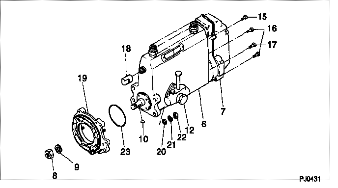
| 000. | [01] | 19000-06900 | PUMP ASSY, INJECTI | ME008332 |
| 006. | [01] | 09010-04861 | BODY ASSY, INJECTI | ME703936 |
| 007. | [01] | 09080-07940 | GOVERNOR ASSY, MEC | |
| 008. | [01] | 09001-20080 | NUT, TIMER ROUND | ME022426 |
| 008. | [01] | 09001-20260 | NUT, TIMER ROUND | ME703450 |
| 009. | [01] | 94901-50500 | WASHER, SPRING | ME008373 |
| 010. | [01] | 94913-00190 | KEY, WOODRUFF | ME703361 |
| 012. | [01] | 09210-01540 | PUMP ASSY, FUEL FE | ME703397 |
| 015. | [01] | 91518-08221 | BOLT, W/WASHER | MM500963 |
| 016. | [05] | 91418-06161 | BOLT, W/WASHER | ME702149 |
| 017. | [01] | 91518-06121 | BOLT, W/WASHER | ME703399 |
| 018. | [01] | 09001-80081 | COVER, CONTROL RAC | ME702034 |
| 019. | [01] | 09006-00140 | COVER SUB-ASSY, TI | ME006130 |
| 020. | [04] | 94901-15020 | WASHER, STEEL PLAT | MH005068 |
| 021. | [04] | 90258-10001 | WASHER, SPRING | MC327716 |
| 022. | [04] | 91266-10081 | NUT, HEXAGON | MF430122 |
| 023. | [01] | 94914-03990 | O-RING | MH035501 |
Include in #3:
19000-06900
as PUMP ASSY, INJECTI
Cross reference number
| Part num | Firm num | Firm | Name |
| 19000-06900 | ME008332 | PUMP ASSY, INJECTI | |
| ME008332 | MITSUBISHI | PUMP ASSY, INJECTI |
Information:
Remove Fuel Injection Pump Housing & Governor
1. Install Tool (A) as shown. 2. Install Tool (B) in the fuel pump housing as shown with the square end down. Use a small amount of hand force to push down on Tool (B) while the fuel control lever is moved forward to the "FUEL ON" position. Rack travel will stop in the center (zero) position. Hold a light forward force on the governor control lever to keep the fuel racks in the center (zero position). 3. Use Tool (A) to turn the engine in a counterclockwise direction (as seen from the flywheel end of the engine) until timing bolt (2) can be installed into the flywheel. The No. 1 piston must be at top center on the compression stroke. If the hole in the flywheel is turned beyond the hole in the flywheel housing, turn the flywheel back (clockwise) a
1. Install Tool (A) as shown. 2. Install Tool (B) in the fuel pump housing as shown with the square end down. Use a small amount of hand force to push down on Tool (B) while the fuel control lever is moved forward to the "FUEL ON" position. Rack travel will stop in the center (zero) position. Hold a light forward force on the governor control lever to keep the fuel racks in the center (zero position). 3. Use Tool (A) to turn the engine in a counterclockwise direction (as seen from the flywheel end of the engine) until timing bolt (2) can be installed into the flywheel. The No. 1 piston must be at top center on the compression stroke. If the hole in the flywheel is turned beyond the hole in the flywheel housing, turn the flywheel back (clockwise) a