Information pump assy, injecti
PUMP ASSY, INJECTI
EA
- THE PUMP ASSY DOES NOT INCLUDE *1.
Nozzle:
0935001830
Rating:
KIT List:
| Body assy, injecti | 1904400300 |
| Governor assy, mec | 1908900250 |
| Timer assy, automa | 0918030050 |
| Pump assy, fuel fe | 1922900060 |
Components :
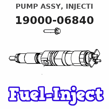
| 001. | PUMP ASSY, INJECTI | 19000-06840 |
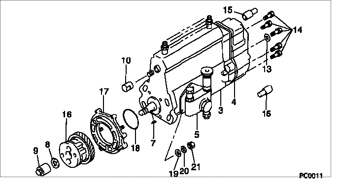
| 002. | BODY ASSY, INJECTI | 09010-02671 |
| 003. | GOVERNOR ASSY, MEC | 09080-08071 |
| 004. | TIMER ASSY, AUTOMA | 09180-01460 |
| 005. | PUMP ASSY, FUEL FE | 09210-01150 |
Scheme ###:
| 000. | [01] | 19000-06840 | PUMP ASSY, INJECTI | |
| 003. | [01] | 09010-02671 | BODY ASSY, INJECTI | ME703961 |
| 004. | [01] | 09080-08071 | GOVERNOR ASSY, MEC | |
| 005. | [01] | 09210-01150 | PUMP ASSY, FUEL FE | ME006015 |
| 007. | [01] | 94913-00190 | KEY, WOODRUFF | ME703361 |
| 008. | [01] | 94901-50500 | WASHER, SPRING | ME008373 |
| 009. | [01] | 09001-20080 | NUT, TIMER ROUND | ME022426 |
| 009. | [01] | 09001-20260 | NUT, TIMER ROUND | ME703450 |
| 010. | [01] | 09001-80190 | COVER, CONTROL RAC | ME022416 |
| 013. | [01] | 90200-06511 | WASHER, PLATE | ME703364 |
| 014. | [06] | 94904-70620 | BOLT, W/WASHER | ME703359 |
| 015. | [02] | 09028-50021 | CAP | ME035845 |
| 016. | [01] | 09180-01460 | TIMER ASSY, AUTOMA | ME006085 |
| 017. | [01] | 09006-00140 | COVER SUB-ASSY, TI | ME006130 |
| 018. | [01] | 94914-03990 | O-RING | MH035501 |
| 019. | [04] | 94901-15020 | WASHER, STEEL PLAT | MH005068 |
| 020. | [04] | 90258-10001 | WASHER, SPRING | MC327716 |
| 021. | [04] | 91266-10081 | NUT, HEXAGON | MF430122 |
Include in #3:
19000-06840
as PUMP ASSY, INJECTI
Cross reference number
| Part num | Firm num | Firm | Name |
| 19000-06840 | PUMP ASSY, INJECTI |
Information:
Remove & Install Fuel Injection Nozzles & Adapters
Later fuel injection nozzles are installed in adapters that are above the surface of the cylinder head. The pictures to follow show the rocker arm shaft removed. This was for better photo illustration. It is not necessary to remove the rocker arm shaft. Start By:a. remove valve covers 1. Use Tool (A) to disconnect fuel injection line (1) at both ends. Remove the fuel injection line from the engine. 2. Use Tool (B) to remove retainer (2) from the adapter.3. Remove the fuel injection nozzles with Tooling (C) as follows:a. Install the 6V-6983 Adapter and the 8T-3199 Screw into nozzle assembly (3).b. Install the 8T-3198 Tube over the 8T-3199 Screw.c. Use the 1B-4206 Nut on the 8T-3199 Screw to pull the fuel injection nozzle from the adapter.4. Remove compression seal (4) and carbon dam seal (8) from fuel injection nozzle (3).5. Use Tool (D) to remove adapter (6) from the cylinder head.6. Remove gasket (7) and seal (5) from adapter (6). The following steps are for installation of the fuel injection nozzles and adapters.7. Use Tool (E) to clean the bore in adapter (6). Use an open end wrench or tap driver to turn Tool (E).8. Inspect seal (5) for damage or wear. Replace the seal if necessary.9. Put washer (7) and seal (5) in position on adapter (6).10. Put liquid soap in the bores of the cylinder head and on seals (5) in the adapters.11. Put 5P-3931 Anti-Seize Compound on the threads of adapter (6), and install the adapter in the cylinder head assembly.12. Use Tool (D), and tighten the adapter to a torque of 205 14 N m (150 10 lb ft).
Make sure the correct compression seal washer (4) is used when the nozzle assembly is installed in the adapter. Only copper washers are to be used with this adapter.
13. Install compression seal washer (4), and use Tool (F) to install carbon dam seal (8) on the fuel injection nozzle.14. Put fuel injection nozzle (3) in position in the adapter, and install retainer (2).15. Use Tool (B) to tighten retainer (2) to a torque of 48 7 N m (35 5 lb ft).16. Install fuel line (1). Tighten the nuts on the fuel line with Tool (A) to a torque of 40 7 N m (30 5 lb ft).End By:a. install valve covers