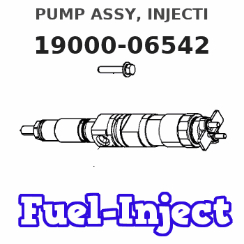
Information pump assy, injecti
Rating:
Components :
| 001. | PUMP ASSY, INJECTI | 19000-06542 |
| 002. | BODY ASSY, INJECTI | 09010-04831 |
| 003. | GOVERNOR ASSY, MEC | 09080-07292 |
| 004. | PUMP ASSY, FUEL FE | 09210-01011 |
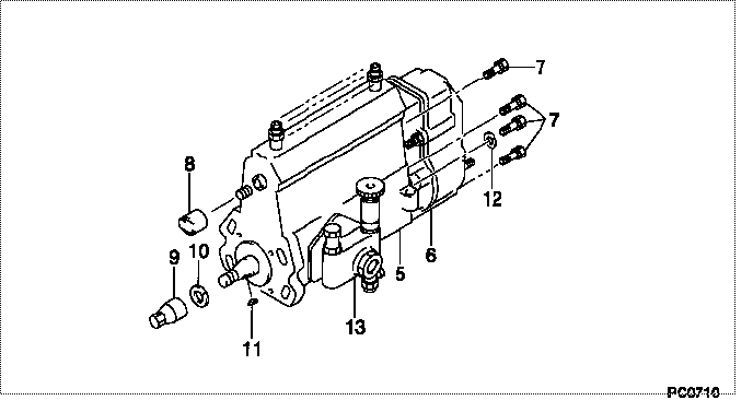
Scheme ###:
| 000. | [01] | 19000-06542 | PUMP ASSY, INJECTI | 34761-52011 |
| 005. | [01] | 09010-04831 | BODY ASSY, INJECTI | |
| 006. | [01] | 09080-07292 | GOVERNOR ASSY, MEC | |
| 007. | [06] | 94904-70620 | BOLT, W/WASHER | |
| 008. | [01] | 09001-80081 | COVER, CONTROL RAC | 09001-80081 |
| 009. | [01] | 09001-20260 | NUT, TIMER ROUND | |
| 009. | [01] | 09001-20080 | NUT, TIMER ROUND | 09001-20080 |
| 010. | [01] | 94901-50500 | WASHER, SPRING | 94901-50500 |
| 011. | [01] | 94913-00190 | KEY, WOODRUFF | 94913-00190 |
| 012. | [01] | 90200-06511 | WASHER, PLATE | |
| 013. | [01] | 09210-01011 | PUMP ASSY, FUEL FE | 34461-00303 |
Include in #3:
19000-06542
as PUMP ASSY, INJECTI
Cross reference number
| Part num | Firm num | Firm | Name |
| 19000-06542 | 34761-5201 | PUMP ASSY, INJECTI |
Information:
Be sure the fuel injection line clamps are installed in the correct locations. Incorrectly installed clamps may allow the fuel injection lines to vibrate and become damaged. The damaged lines may leak and cause a fire.
(1) Clamp location dimensions are in reference to a vertical line (1) through the center of the number one fuel pump outlet. Align brackets in position to fuel lines such that when the fasteners are tightened no strain will be added to the fuel lines while tightening fasteners.(A) ... 35 3 mm (1.38 .12 in)(B) ... 165 13 mm (6.50 .51 in)(C) ... 187 1 mm (7.36 .04 in)(D) ... 187 3 mm (7.36 .12 in)(E) ... 282 3 mm (11.10 .12 in)(F) ... 314 13 mm (12.36 .51 in)(G) ... 457 3 mm (17.99 .12 in)(H) ... 529 3 mm (17.99 .12 in)Tighten metal-to-metal clamps to a torque of ... 2.3 N m (20 lb in) The 6V4980 Torque Screwdriver Tool Group is available for applying the correct torque. (2) Tighten fuel injection line nuts to ... 42 7 N m (31 5 lb ft)(3) Tighten nuts to ... 14 3 N m (10 2 lb ft)(4) Tighten retainer on adapter to ... 48 7 N m (35 5 lb ft)
Fuel Injection Line With Support Bracket
Be sure the fuel injection line clamps are installed in the correct locations. Incorrectly installed clamps may allow the fuel injection lines to vibrate and become damaged. The damaged lines may leak and cause a fire.
(1) Clamp location dimensions are in reference to a vertical line (1) through the center of the number one fuel pump outlet.Align brackets in position to fuel lines such that when the fasteners are tightened no strain will be added to the fuel lines while tightening fasteners.(A) ... 35 3 mm (1.38 .12 in)(B) ... 165 13 mm (6.50 .51 in)(C) ... 187 1 mm (7.36 .04 in)(D) ... 187 3 mm (7.36 .12 in)(E) ... 282 3 mm (11.10 .12 in)(F) ... 283 3 mm (11.14 .12 in)(G) ... 529 3 mm (17.99 .12 in)Tighten metal-to-metal clamps to a torque of ... 2.3 N m (20 lb in) The 6V4980 Torque Screwdriver Tool Group is available for applying the correct torque. (2) Tighten fuel injection line nuts to ... 42 7 N m (31 5 lb ft)(3) Tighten nuts to ... 14 3 N m (10 2 lb ft)(4) Tighten retainer on adapter to ... 48 7 N m (35 5 lb ft)