Information pump assy, injecti
Nozzle:
0935002080
Rating:
KIT List:
| Body assy, injecti | 1904400360 |
| Governor assy, mec | 1908900190 |
| Timer assy, automa | 0918030060 |
| Pump assy, fuel fe | 1922900060 |
Components :
| 001. | PUMP ASSY, INJECTI | 19000-06330 |
| 002. | BODY ASSY, INJECTI | 09010-04232 |
| 003. | COVER, BEARING | 09020-10410 |
| 004. | GOVERNOR ASSY, MEC | 09080-07040 |
| 005. | TIMER ASSY, AUTOMA | 09180-01210 |
| 006. | PUMP ASSY, FUEL FE | 09210-00920 |
| 007. | COUPLING ASSY | 09250-00270 |
Scheme ###:
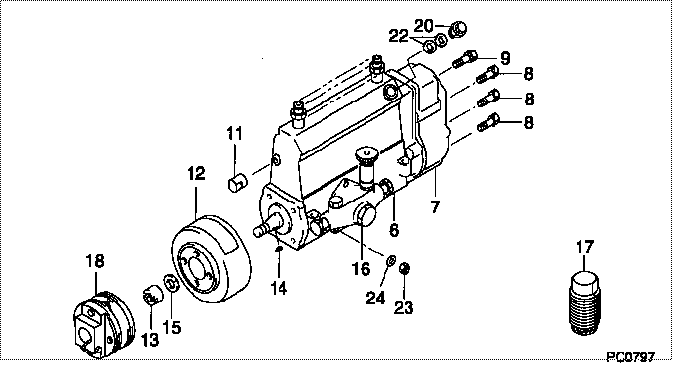
| 000. | [01] | 19000-06330 | PUMP ASSY, INJECTI | 22010-2920 |
| 006. | [01] | 09010-04232 | BODY ASSY, INJECTI | 22110-1590C |
| 007. | [01] | 09080-07040 | GOVERNOR ASSY, MEC | 22310-2220 |
| 008. | [06] | 94904-71150 | BOLT, W/WASHER | 6 306 1001 00 |
| 009. | [01] | 94904-73910 | BOLT, W/WASHER | 22815-2820A |
| 011. | [01] | 09001-80290 | COVER, CONTROL RAC | 22114-1020A |
| 012. | [01] | 09180-01210 | TIMER ASSY, AUTOMA | 22510-1190A |
| 013. | [01] | 09001-20180 | NUT, TIMER ROUND | 22511-1070A |
| 014. | [01] | 94913-00210 | KEY, WOODRUFF | 22895-1010A |
| 015. | [01] | 94901-50590 | WASHER, SPRING | 22877-1620A |
| 016. | [01] | 09210-00920 | PUMP ASSY, FUEL FE | 22570-1250A |
| 017. | [01] | 09006-10020 | COVER, PRIMING PUM | 22561-1020 |
| 018. | [01] | 09250-00270 | COUPLING ASSY | 22610-1080A |
| 020. | [01] | 09031-00130 | VALVE ASSY, OVERFL | 22107-1090A |
| 022. | [02] | 94901-02480 | WASHER | 22847-1940A |
| 023. | [03] | 90160-06051 | NUT, HEXAGON | 22825-1480A |
| 024. | [03] | 90258-06001 | WASHER, SPRING | 28219-1110A |
Include in #3:
19000-06330
as PUMP ASSY, INJECTI
Cross reference number
| Part num | Firm num | Firm | Name |
| 19000-06330 | 22010-2920 | PUMP ASSY, INJECTI | |
| 22010-2920 | HINO | PUMP ASSY, INJECTI |
Information:
Keep all parts clean from contaminants. Contaminants put into the system may cause rapid wear and shortened component life.
1. Bend the lock tab and remove bolt (1).
The oil pump idler gear (3) can fall off the pump when the pump is removed. Injury can be the result. To prevent injury, always hold idler gear on the pump when the pump is removed.
2. Bend the two tabs on locks (4) on the left hand side of the engine. Remove the four bolts (2) and (5) and remove the oil pump and suction bell as a unit. Be sure the idler gear (3) is engaged with the crankshaft gear and tabs on locks (4) on bolts (5) are not next to the oil pan gasket surface when bolts (2) and (5) are tightened. Install in reverse order.End By:a. install oil panDisassemble Oil Pump
Start By:a. remove oil pump
Keep all parts clean from contaminants. Contaminants put into the system may cause rapid wear and shortened component life.
1. Remove idler gear (2). Remove the bearing from the idler gear with tooling (B).2. Remove suction bell (1) and the bolt and the washer from the oil pump drive gear. 3. Remove the drive gear from the shaft with tooling (A).4. Remove the key from the pump shaft and bolts (3). 5. Remove body (8), two gears (7), the keys and spacer (4).6. Remove two shafts (5) and the gears.7. Remove bolts (6), the cover and the pressure relief valve. 8. Remove the bearings from the oil pump body assembly and the scavenge pump body assembly with tooling (B).Assemble Oil Pump
1. Install the bearings in the scavenge pump body assembly with tooling (B) and a press as follows:a. Put bearings (9) in position on the inside of the scavenge pump body assembly with the chamfer on the bearing toward the outside of the pump body. Install the bearing until it is 1.52 mm (.060 in) below the inside machined surface of the scavenge pump body assembly. Make sure the joints in the bearings are at an angle of 30° 15° from the center line through the bores in the scavenge pump body and toward the outlet passage of the pump. The outlet passage has a cavity between the bearing bores. 2. Install the bearings in oil pump body assembly with tooling (B) and a press as follows.a. Put bearings (10) in position on the inside of the oil pump body assembly with the chamfer on the bearings toward the outside of the pump body. Install the bearings until they are even with the outside of the pump at an angle of 30° 15° from the centerline through the bearing bores and toward the outlet passage of the pump. The outlet passage has a cavity between the bearing bores.3. Check the condition of the relief valve. Check the condition and specifications for all the parts of the oil pump before it is assembled. See the topic, Oil Pump, in the Specifications module.4. Put clean