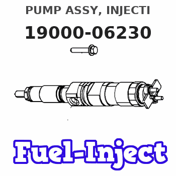
Information pump assy, injecti
PUMP ASSY, INJECTI
AA
- * THIS PUMP IS A SPAIR PUMP OF 093000-0270
- (WITHOUT TIMER).
Nozzle:
0935001810
Rating:
KIT List:
| Timer assy, automa | 0918030050 |
| Pump assy, fuel fe | 1922900060 |
Components :
| 001. | PUMP ASSY, INJECTI | 19000-06230 |
| 002. | BODY ASSY, INJECTI | 09010-04320 |
| 003. | TIMER ASSY, AUTOMA | 09180-01540 |
| 004. | PUMP ASSY, FUEL FE | 09210-00971 |
Scheme ###:
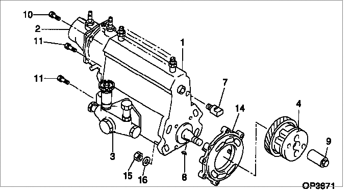
| 000. | [01] | 19000-06230 | PUMP ASSY, INJECTI | 22100-68090 |
| 001. | [01] | 09010-04320 | BODY ASSY, INJECTI | 22120-68010 |
| 002. | [01] | 09070-00462 | GOVERNOR ASSY, COM | 22320-68090 |
| 003. | [01] | 09210-00971 | PUMP ASSY, FUEL FE | 22510-77130 |
| 004. | [01] | 09180-01540 | TIMER ASSY, AUTOMA | 26106-8020 |
| 007. | [01] | 09001-80061 | COVER, CONTROL RAC | 22116-46010 |
| 008. | [01] | 94913-00190 | KEY, WOODRUFF | 90099-13020 |
| 009. | [01] | 09001-20260 | NUT, TIMER ROUND | 22611-68010 |
| 010. | [01] | 91518-08221 | BOLT, W/WASHER | 90091-20804 |
| 011. | [04] | 94904-70620 | BOLT, W/WASHER | 90099-04526 |
| 014. | [01] | 09006-00100 | COVER SUB-ASSY, TI | 22812-68010 |
| 015. | [04] | 91260-10081 | NUT, HEXAGON | 94110-41000 |
| 016. | [04] | 94901-17570 | WASHER, STEEL PLAT | 90201-10018 |
| 016. | [04] | 94901-15020 | WASHER, STEEL PLAT | 90099-01468 |
Include in #3:
19000-06230
as PUMP ASSY, INJECTI
Cross reference number
| Part num | Firm num | Firm | Name |
| 19000-06230 | 22100-6809 | PUMP ASSY, INJECTI | |
| 22100-68090 | TOYOTA | PUMP ASSY, INJECTI |
Information:
The turbocharger does not have to be removed from the engine in order to remove the wastegate.1. Remove two clamps (1) and hose (2). 2. Remove retainer (4) and two nuts (3). 3. Remove three mounting bolts (6) and bracket (5).Disassemble Turbocharger (Schweitzer S4A)
Start By:a. remove turbocharger 1. Install the turbocharger on tool (A) as shown.2. Put alignment marks on three housings of the turbocharger for correct alignment during assembly. Loosen clamp (2), and remove the clamp and housing (1) from housing assembly (3). 3. Loosen clamp (4), and remove housing assembly (3) from housing (5). 4. Put the cartridge group in position in tool (B) as shown.
When the nut is loosened, do not put a side force on the shaft. This can result in a bent shaft.
5. Use a 5S9566 Sliding T-Wrench and a universal socket (6) to remove the nut that holds the compressor wheel to the wheel assembly.6. Remove compressor wheel (7) and the shims from wheel assembly (8).7. Remove housing assembly (3). 8. Remove ring (9) and backplate (10). 9. Use tool (C), and remove snap ring (11). 10. Remove insert (12) and sleeve (13). 11. Remove ring (14). 12. Remove two screws (15) and deflector (16). 13. Remove ring (18) and bearing assembly (17). 14. Remove sleeve (19) and ring (20). 15. Remove O-ring seal (23). Use tool (D), and remove snap ring (22).16. Remove bearing (21). Remove the snap ring behind the bearing with tool (D). 17. Use tool (D), and remove snap ring (25). Remove bearing (24). Remove the snap ring behind the bearing with tool (D).18. Check all the parts of the turbocharger for damage. If the parts are damaged, use new parts for replacement. See Special Instruction, Form No. SMHS6854, for Turbocharger Reconditioning. Also, see Guidelines For Reusable Parts, Form No. SEBF8018.Assemble Turbocharger (Schweitzer S4A)
1. Make sure that all of the oil passages in the turbocharger cartridge housing are clean and free of dirt and foreign material. Do not put oil on any parts of the turbocharger until after the compressor wheel has been installed. After the turbocharger has been assembled, pour clean engine oil into the oil inlet of the turbocharger.
Make sure that the snap rings that hold bearings (24) and (21) in position in housing assembly (3) are installed with the round edge of the outside diameter toward the bearing.
2. Install the snap ring behind bearing (24) with tool (D). Install bearing (24).3. Use tool (D), and install snap ring (25). 4. Install the snap ring behind bearing (21) with tool (D). Install bearing (21).5. Use tool (D), and install snap ring (22). 6. Put wheel assembly (8) in position on tool (B) as shown. Put backplate (10) in position on the wheel assembly. Put 6V2055 High Vacuum Grease in the groove for seal ring (9) at assembly to one half or more of the depth of the groove all the way around.7. Install ring (9) in the groove in wheel assembly (8). 8. Install housing