Information pump assy, injecti
Rating:
Components :
| 001. | PUMP ASSY, INJECTI | 19000-05911 |
| 002. | BODY ASSY, INJECTI | 09010-04491 |
| 003. | COVER, BEARING | 09020-10110 |
| 004. | TIMER ASSY, AUTOMA | 09180-01421 |
| 005. | PUMP ASSY, FUEL FE | 09210-01900 |
| 006. | COUPLING ASSY | 09250-00631 |
Scheme ###:
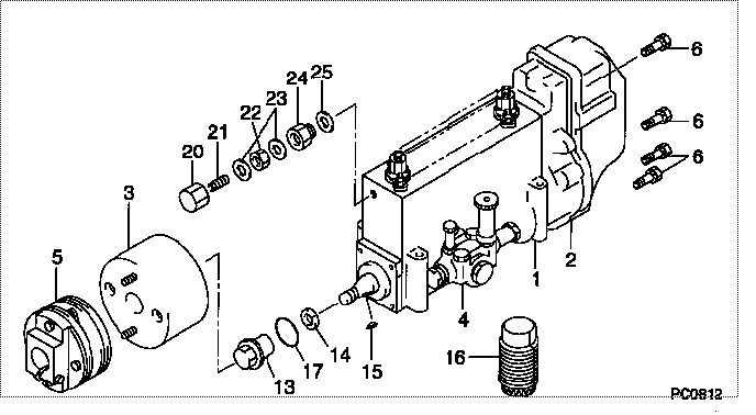
| 000. | [01] | 19000-05911 | PUMP ASSY, INJECTI | 22010-2830 |
| 001. | [01] | 09010-04491 | BODY ASSY, INJECTI | 22110-1680 |
| 002. | [01] | 09080-06972 | GOVERNOR ASSY, MEC | 22310-2110 |
| 003. | [01] | 09180-01421 | TIMER ASSY, AUTOMA | 22510-1450 |
| 004. | [01] | 09210-01900 | PUMP ASSY, FUEL FE | 22570-1330A |
| 005. | [01] | 09250-00631 | COUPLING ASSY | 22610-1471A |
| 006. | [08] | 91518-06161 | BOLT, W/WASHER | 22815-1310A |
| 013. | [01] | 09001-20230 | NUT, TIMER ROUND | 22825-1110A |
| 014. | [01] | 94901-40070 | WASHER, COUNTERSUN | 22877-1190A |
| 015. | [01] | 90458-05750 | KEY, WOODRUFF | 22891-1070A |
| 016. | [01] | 09006-10030 | COVER, PRIMING PUM | 22561-1040 |
| 017. | [01] | 90801-40280 | O-RING | 22817-1050A |
| 020. | [01] | 09003-20040 | CAP | 22342-1110A |
| 021. | [01] | 09002-60050 | SCREW, ADJUSTING | 22396-1140A |
| 022. | [01] | 94805-30100 | NUT, HEXAGON, W/HO | 22885-3830A |
| 023. | [02] | 94901-80350 | WASHER, COPPER PLA | 22847-1950A |
| 024. | [01] | 09001-80152 | COVER, CONTROL RAC | 22372-1100A |
| 025. | [01] | 94901-80710 | WASHER, COPPER PLA | 22863-1300A |
Include in #3:
19000-05911
as PUMP ASSY, INJECTI
Cross reference number
| Part num | Firm num | Firm | Name |
| 19000-05911 | 22010-2830 | PUMP ASSY, INJECTI |
Information:
Remove Pistons & Connecting Rod Assemblies
Start By:a. remove cylinder head assemblyb. remove oil pumpc. remove piston cooling tubes1. Remove the carbon ridge from the top inside surface of the cylinder liners. 2. Turn the crankshaft until two pistons are at bottom center.3. Remove bolts (1) and the bearing caps. Push the rods and pistons up until the rings are out of the cylinder liners. 4. Remove pistons (2) and connecting rods from the cylinder liners.5. Do Steps 1 through 4 for the remainder of the pistons and connecting rods.Install Pistons & Connecting Rod Assemblies
1. Put clean engine oil on piston rings, connecting rod bearings and cylinder liners. 2. Use Tool (A), and install piston (2) and the connecting rod in the cylinder liner.3. Install the bearing cap on the connecting rod with the number on the side of the bearing cap on the same side and same number as on the connecting rod.4. Put 2P2506 Thread Lubricant on the threads of the bolts. Install the nuts, and tighten them to a torque of 90 8 N m (67 6 lb ft). Put a mark on the nuts and cap, and tighten the nuts an extra 90 5 degrees.5. Do Steps 1 through 4 for the remainder of the pistons and connecting rods.End By:a. install piston cooling tubesb. install oil pumpc. install cylinder head assemblyDisassemble & Assemble Pistons & Connecting Rod Assemblies
Start By:a. remove pistons and connecting rod assemblies 1. Remove bearings (3) from the connecting rod and connecting rod cap.2. Remove retainer ring (1) with Tool (A).3. Remove pin (2) and connecting rod (4) from the piston. 4. Remove piston rings (5) from the piston with Tool (B). Clean the piston ring grooves