Information pump assy, injecti
Nozzle:
0935001850

Rating:
KIT List:
| Pump assy, fuel fe | 1922900060 |
Components :
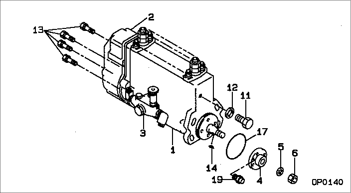
| 001. | PUMP ASSY, INJECTI | 19000-05890 |
| 002. | BODY ASSY, INJECTI | 09010-04691 |
| 003. | PUMP ASSY, FUEL FE | 09210-01710 |
Scheme ###:
| 000. | [01] | 19000-05890 | PUMP ASSY, INJECTI | AR99858 |
| 001. | [01] | 09010-04691 | BODY ASSY, INJECTI | |
| 002. | [01] | 09080-06960 | GOVERNOR ASSY, MEC | |
| 003. | [01] | 09210-01710 | PUMP ASSY, FUEL FE | |
| 004. | [01] | 09255-10280 | BLOCK, COUPLING | |
| 005. | [01] | 94901-50730 | WASHER, SPRING | |
| 006. | [01] | 94905-03400 | NUT, HEXAGON | |
| 011. | [01] | 09001-80110 | COVER, CONTROL RAC | |
| 012. | [01] | 94901-80710 | WASHER, COPPER PLA | |
| 013. | [08] | 91418-06201 | BOLT, W/WASHER | |
| 014. | [01] | 90458-05750 | KEY, WOODRUFF | |
| 017. | [01] | 94914-02700 | O-RING | |
| 019. | [01] | 94904-05241 | BOLT, HEXAGON |
Include in #3:
19000-05890
as PUMP ASSY, INJECTI
Cross reference number
| Part num | Firm num | Firm | Name |
| 19000-05890 | AR99858 | PUMP ASSY, INJECTI | |
| AR99858 | JOHN DEERE | PUMP ASSY, INJECTI |
Information:
1. Drain the cooling system. 2. Loosen hose clamps (1) and (3). Disconnect hoses (2) and (4). 3. Support pump (5) and remove four bolts (6). 4. Remove elbow (7) and the gasket. The following steps are to install the water pump.5. Install a new gasket and elbow (7).6. Put the water pump (5) and elbow (7) in position and install four bolts (6).7. Put hoses (2) and (4) in position on elbow (7) and tighten the clamps (1) and (3).8. Fill the cooling system to the correct level. See the Maintenance Manual.Disassemble And Assemble Water Pump
Start By:a. remove water pump
Keep all parts clean from contaminants. Contaminants put into the system may cause rapid wear and shortened component life.
1. Remove bolt (15) and the washer. Remove bearing (12) and gear (10) as a unit.2. Use tooling (A), (C) and a press, and remove bearing (12) from gear (10).3. Remove snap ring (8) with tool (B).4. Remove two bolts (1), the washers, cover (14) and gasket (2) from water pump housing (18).5. Loosen bolt (13) approximately 6.4 mm (.25 in). Hit the bolt with a soft hammer to loosen impeller (16).6. Remove bolt (13), washer (11), impeller (16), spring (3) and seal assembly (4).7. Remove bearing (7) and shaft (9) as a unit.8. Use tooling (A), (C) and a press to remove bearing (7).9. Remove ceramic seal (5) and seal (17).10. Use tool (C) to remove lip-type seal (6). The following steps are for assembly of the water pump.11. Install hydrodynamic seal (6) in water pump housing (18) with tool (C). The lip of the seal must be toward the bearings. Put clean engine oil on the lip of the seal.12. Install shaft (9) in bearing (7) with a press.13. Install shaft (9) and bearing (7) as a unit in water pump housing (18).14. Install snap ring (8) with tool (B).
Clean water only is permitted for use as a lubricant for assembly. Do not damage or put hands on the wear surface of the carbon ring or the ceramic ring. Install the ceramic ring with the smoothest face of the ring toward the carbon seal assembly.
15. Put ceramic ring (5) in position in seal (17). Use hand pressure and tool (D) to install the ceramic ring.16. Remove spring (3) from seal assembly (4). Use hand pressure and tool (D) to install the seal assembly. Push seal assembly (4) on shaft (9) until it makes light contact with ceramic ring (5).17. Install spring (3) on seal assembly (4). Put impeller (16) in position on shaft (9), and install washer (11) and bolt (13). Tighten bolt (13) to a torque of 38.0 1.5 N m (28 1 lb ft).18. Put gasket (2) and cover (14) in position and install the two washers and bolts (1).19. Install bearing (12) on gear (10) with a press.20. Position gear (10) and bearing (12) as a unit on shaft (9). Install the washer and bolt (15). Torque bolt (15) to 97 7