Information pump assy, injecti
Rating:
KIT List:
| Pump assy, fuel fe | 1922900060 |
Components :
| 001. | PUMP ASSY, INJECTI | 19000-05840 |
| 002. | SWITCH KIT, CONTRO | 09009-90130 |
| 003. | BODY ASSY, INJECTI | 09010-02830 |
| 004. | COVER, BEARING | 09020-10053 |
| 005. | TIMER ASSY, AUTOMA | 09180-01200 |
| 006. | PUMP ASSY, FUEL FE | 09210-00930 |
| 007. | COUPLING ASSY | 09250-00321 |
Scheme ###:
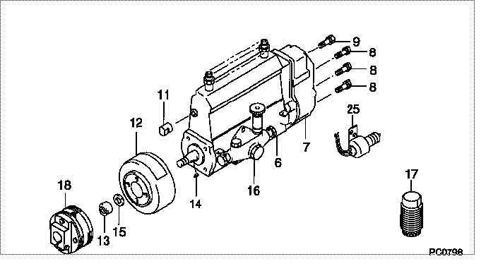
| 000. | [01] | 19000-05840 | PUMP ASSY, INJECTI | 22010-2810 |
| 006. | [01] | 09010-02830 | BODY ASSY, INJECTI | |
| 007. | [01] | 09080-06940 | GOVERNOR ASSY, MEC | |
| 008. | [06] | 94904-71150 | BOLT, W/WASHER | 6 306 1001 00 |
| 009. | [01] | 94904-73910 | BOLT, W/WASHER | 22815-2820A |
| 011. | [01] | 09001-80081 | COVER, CONTROL RAC | 22114-1130A |
| 012. | [01] | 09180-01200 | TIMER ASSY, AUTOMA | 22510-1180A |
| 013. | [01] | 09001-20010 | NUT, TIMER ROUND | 22353-1050A |
| 014. | [01] | 94913-00050 | KEY, WOODRUFF | 22891-1040A |
| 015. | [01] | 90258-12001 | WASHER, SPRING | 22873-1310A |
| 016. | [01] | 09210-00930 | PUMP ASSY, FUEL FE | 22570-1040A |
| 017. | [01] | 09006-10011 | COVER, PRIMING PUM | 6 053 1552 60 |
| 018. | [01] | 09250-00321 | COUPLING ASSY | 22610-1131 |
| 025. | [01] | 09009-90130 | SWITCH KIT, CONTRO | 22690-1020 |
Include in #3:
19000-05840
as PUMP ASSY, INJECTI
Cross reference number
| Part num | Firm num | Firm | Name |
| 19000-05840 | 22010-2810 | PUMP ASSY, INJECTI | |
| 22010-2810 | HINO | PUMP ASSY, INJECTI |
Information:
Keep all parts clean from contaminants. Contaminants put into the system may cause rapid wear and shortened component life.
Illustration shows the fuel shutoff solenoid and the tachometer adapter removed.1. Remove six bolts (1), two top bolts (2), housing (3) and the gasket. 2. Remove governor spring (4) and seat (5). 3. Remove bolts (6), cover (7) and the gasket. Use tool (A) to remove seal (8). 4. Remove low idle adjustment screw (9) and spring (10). 5. Remove shaft assembly (12) and levers (11) and (13). 6. Remove the two snap rings from pins (15) and remove pins (15). Remove plates (14) and stop (16). 7. Remove pins (18) and (17) and spring (19). 8. Remove two bolts (20) adapter (22), the coupling, and the O-ring seal.9. Remove contact (23) and body (24).10. Remove two bolts (25), cover (27), and the gasket.11. Remove two bolts (21), shutoff solenoid (26), and the gasket. 12. Remove shaft (28) and lever (29).
The check valve will be damaged during removal. Remove check valve (30) only if a replacement is necessary.
13. Remove check valve (30) if a replacement is necessary. 14. Remove seal (31) and adjustment screw (32).
Typical Example15. Remove bolt (33), housing (34), and the gasket from the fuel injection pump housing. 16. Remove bolts (35) and torque control group (36).17. Disassemble the torque control group and inspect the spacer, the spring and the insulator for damage or wear. 18. Remove two bolts (38) and block (37). 19. Remove the bolt that holds collar (39) to bolt (40). Remove collar (39), spring (41) and bolt (40).20. Remove the stop screw from collar (39) if a replacement is necessary. 21. Remove bolts (42) and governor servo (43). 22. Remove lockring (48), seat (47), spring (broken link spring) (46) and sleeve (45). Remove the other lockring (48) from the groove in the center of valve (44). 23. Remove valve (44), sleeve (49) and piston (51). Remove the O-ring seal from sleeve (49).24. Remove pin (50) and lever (52). 25. Use tool (B) to hold spring (54) in compression for removal of ring (53). Spring (54) is used to put a preload on the thrust bearing for the camshaft in the fuel injection pump housing.26. Remove ring (53) and tool (B). 27. Remove bearing (55), sleeves (56) and spring (54). 28. Remove ring (57) and dashpot assembly (58). 29. Use tool (C) to remove snap ring (64). Remove ring (63) and spool (62).30. Remove seat (61) from spring (60) and remove spring (60) from seat (59). 31. Remove spring (overfueling spring) (65) and riser (66). 32. Remove ring (67), races (68) and bearing (69). Make a replacement of shield (70) any time it is removed.33. Use a screwdriver to remove shield (70) as shown. 34. Remove bolts (71) and carrier (72). 35. Remove dowels (73) and flyweights (75).36. Remove shaft (74) and the dowel from shaft (74). 37. Remove races (76) and bearing (77).Assemble Governor
Put clean oil on all parts before assembly. Be sure all