Information pump assy, injecti
Rating:
Components :
| 001. | PUMP ASSY, INJECTI | 19000-05412 |
| 002. | BODY ASSY, INJECTI | 09010-04320 |
| 003. | GOVERNOR ASSY, COM | 09070-00372 |
| 004. | TIMER ASSY, AUTOMA | 09180-01330 |
| 005. | PUMP ASSY, FUEL FE | 09210-00971 |
Scheme ###:
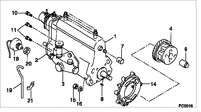
| 000. | [01] | 19000-05412 | PUMP ASSY, INJECTI | 22100-68030 |
| 001. | [01] | 09010-04320 | BODY ASSY, INJECTI | 22120-68010 |
| 002. | [01] | 09070-00372 | GOVERNOR ASSY, COM | 22320-68030 |
| 003. | [01] | 09210-00971 | PUMP ASSY, FUEL FE | 22510-77130 |
| 004. | [01] | 09180-01330 | TIMER ASSY, AUTOMA | 22610-68010 |
| 007. | [01] | 09001-80061 | COVER, CONTROL RAC | 22116-46010 |
| 008. | [01] | 94913-00190 | KEY, WOODRUFF | 90099-13020 |
| 009. | [01] | 09001-20260 | NUT, TIMER ROUND | 22611-68010 |
| 010. | [01] | 91518-08221 | BOLT, W/WASHER | 90091-20804 |
| 011. | [04] | 94904-70620 | BOLT, W/WASHER | 90099-04526 |
| 014. | [01] | 09006-00100 | COVER SUB-ASSY, TI | 22812-68010 |
| 015. | [04] | 91260-10081 | NUT, HEXAGON | 94110-41000 |
| 016. | [04] | 94901-17570 | WASHER, STEEL PLAT | 90201-10018 |
| 018. | [01] | 09071-00011 | BELLOWS ASSY, PNEU | 22680-48061 |
| 019. | [01] | 94933-03581 | TUBE, RUBBER | 90099-33044 |
| 020. | [01] | 94905-61980 | NUT | 90099-05154 |
| 021. | [01] | 94935-03042 | CLIP, CORD | 90099-35023 |
Include in #3:
19000-05412
as PUMP ASSY, INJECTI
Cross reference number
| Part num | Firm num | Firm | Name |
| 19000-05412 | 22100-6803 | PUMP ASSY, INJECTI |
Information:
1. Remove bolts (1) and remove the oil pump pick-up and discharge tubes. 2. Remove two bolts (2) and remove the oil pump. The following step is for the installation of the oil pump.3. Position the oil pump and install and torque two bolts (2).4. Position the pick-up and discharge tubes and install bolts (1).End By:a. install oil panDisassemble And Assemble Oil Pump
Start By:a. remove oil pump 1. If necessary, remove the idler gear.2. Remove bolt (1) and remove relief valve spring (2) with relief valve (3).4. Use tooling (A) and remove input gear (4).
Before removing the input shaft and gear from the pump housing, be sure no burrs are on the input shaft. Burrs on the shaft may scratch and damage the pump housing.
5. Remove bolts (5) and separate the pump housing. Remove input shaft and gear (6) from the pump housing. Remove the driven gear from the housing. The following steps are for the assembly of the oil pump. Before pressing input gear (4) onto input shaft (6) be sure to install bolt (5), that is positioned under the input gear.6. Position input gear and shaft (6) in the pump housing. Press input gear (4) onto the input shaft until it is flush with the end of the shaft. Position the driven gear in the housing.7. Position the pump housings together. Install bolts (5). Install the idler gear if it was removed.8. Position relief valve spring (2), relief valve (3) and install bolt (1).End By:a. install oil pump