Information pump assy, injecti
Nozzle:
0935001180
Rating:
KIT List:
| Body assy, injecti | No Application |
| Governor assy, mec | No Application |
| Pump assy, fuel fe | 1922900060 |
Components :
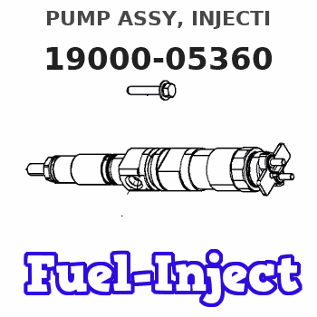
| 001. | PUMP ASSY, INJECTI | 19000-05360 |
| 002. | BODY ASSY, INJECTI | 09010-04540 |
| 003. | GOVERNOR ASSY, MEC | 09080-06670 |
| 004. | PUMP ASSY, FUEL FE | 09210-01411 |
Scheme ###:
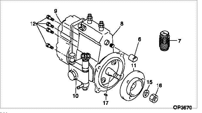
| 000. | [01] | 19000-05360 | PUMP ASSY, INJECTI | 131016790 |
| 006. | [01] | 09001-80140 | COVER, CONTROL RAC | |
| 007. | [01] | 09006-10011 | COVER, PRIMING PUM | |
| 008. | [01] | 09010-04540 | BODY ASSY, INJECTI | |
| 009. | [01] | 09080-06670 | GOVERNOR ASSY, MEC | |
| 010. | [01] | 09210-01411 | PUMP ASSY, FUEL FE | |
| 011. | [01] | 09255-10181 | BLOCK, COUPLING | |
| 012. | [06] | 94904-70620 | BOLT, W/WASHER | |
| 015. | [01] | 90258-12001 | WASHER, SPRING | |
| 016. | [01] | 94905-02450 | NUT, HEXAGON | |
| 017. | [01] | 94913-00190 | KEY, WOODRUFF |
Include in #3:
19000-05360
as PUMP ASSY, INJECTI
Cross reference number
| Part num | Firm num | Firm | Name |
| 19000-05360 | 131016790 | PUMP ASSY, INJECTI | |
| 131016790 | ISHIKAWAJIMA | PUMP ASSY, INJECTI |
Information:
1. Loosen bolts (1) and (2) on belt tightener (3), remove belt (4). 2. Loosen the hose clamp at the water temperature regulator and the water pump. Remove four bolts (5) and remove water pump. The following steps are for the installation of the water pump and belt.3. Position the water pump with two o-ring seals (6) in place. Install four bolts (5) and tighten evenly. Tighten the hose clamp at the water temperature regulator and the water pump.4. Use a breaker bar in square drive slot (7) to apply belt tension, then tighten bolts (1) and (2). To adjust belt to proper tension, see the V-Belt Tension Chart in the Specifications section of this service manual for the correct tension on the belt.End By:a. install belt (Poly-Rib) and tensionerDisassemble And Assemble Water Pump
Start By:a. remove water pump and belt 1. Remove four bolts and remove rear cover (1) with gasket from the water pump.
When pressing the water pump apart do not allow the shaft and pulley to fall to the floor, damage may occur to the pulley.
2. Position water pump in a press. Use spacer plates to level the water pump. Using a small plate from Driver Set (A), press shaft (2) and pulley (3) out of impeller (4). Remove impeller (4).3. Continue to press shaft (2) and pulley (3) out of seal (5) and the water pump housing.4. Use the handle from Driver Set (B) to remove seal (5) from the water pump housing.5. Press shaft (2) and bearing assembly from pulley (3). The following steps are for the assembly of the water pump.6. Press shaft (2) and bearing assembly into pulley (3) until the end of the shaft is flush with the pulley (as illustrated).7. Press shaft (2) and bearing assembly with pulley (3) into water pump housing to the correct pulley position (as illustrated).8. Using Water Pump Seal Installer (C), install seal (5). Press impeller (4) onto shaft (2) to the correct impeller position (as illustrated).9. Position gasket and cover (1) and install the four bolts.End By:a. install water pump and belt