Information pump assy, injecti
Nozzle:
0935000810

Rating:
KIT List:
| Governor assy, mec | 1908900190 |
Components :
| 001. | PUMP ASSY, INJECTI | 19000-05080 |
| 002. | BODY ASSY, INJECTI | 09010-03270 |
| 003. | COVER, BEARING | 09020-10053 |
| 004. | GOVERNOR ASSY, MEC | 09080-06480 |
| 005. | TIMER ASSY, AUTOMA | 09180-01221 |
| 006. | PUMP ASSY, FUEL FE | 09210-00441 |
| 007. | COUPLING ASSY | 09240-00043 |
Scheme ###:
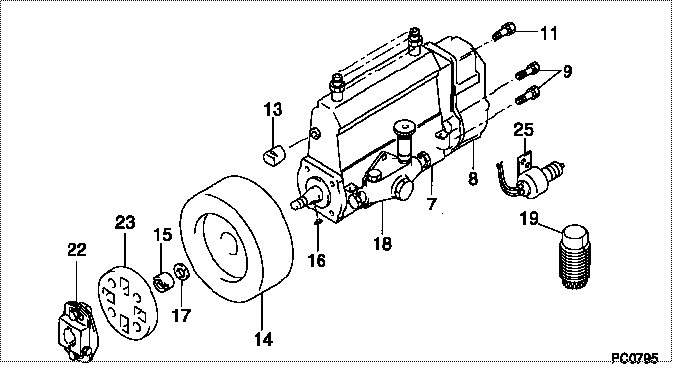
| 000. | [01] | 19000-05080 | PUMP ASSY, INJECTI | 22010-2630 |
| 007. | [01] | 09010-03270 | BODY ASSY, INJECTI | 22110-1160A |
| 008. | [01] | 09080-06480 | GOVERNOR ASSY, MEC | |
| 009. | [06] | 94904-71150 | BOLT, W/WASHER | 6 306 1001 00 |
| 011. | [01] | 94904-73910 | BOLT, W/WASHER | 22815-2820A |
| 013. | [01] | 09001-80120 | COVER, CONTROL RAC | 22371-1170A |
| 014. | [01] | 09180-01221 | TIMER ASSY, AUTOMA | 22510-1220A |
| 015. | [01] | 09001-20010 | NUT, TIMER ROUND | 22353-1050A |
| 016. | [01] | 94913-00050 | KEY, WOODRUFF | 22891-1040A |
| 017. | [01] | 90258-12001 | WASHER, SPRING | 22873-1310A |
| 018. | [01] | 09210-00441 | PUMP ASSY, FUEL FE | 22570-1161A |
| 019. | [01] | 09006-10011 | COVER, PRIMING PUM | 6 053 1552 60 |
| 022. | [01] | 09240-00043 | COUPLING ASSY | 22610-1090A |
| 023. | [01] | 09243-60020 | COUPLING, INJECTIO | 22612-1020A |
Include in #3:
19000-05080
as PUMP ASSY, INJECTI
Cross reference number
| Part num | Firm num | Firm | Name |
| 19000-05080 | 22010-2630 | PUMP ASSY, INJECTI | |
| 22010-2630 | HINO | PUMP ASSY, INJECTI |
Information:
Start By:a. remove flywheel housingb. remove oil pan platec. remove camshaft
Keep all parts clean from contaminants. Contaminants put into the system may cause rapid wear and shortened component life.
1. Remove the camshaft bearings from the cylinder block with tooling (A). Start with the front bearing and work to the rear. The following steps are for the installation of the camshaft bearings.2. Use tooling (A) to install the camshaft bearings in the cylinder block. 3. Install the camshaft bearings in the cylinder block as follows:a. Install the front bearing to a depth of 0.5 0.5 mm (.02 .02 in) and with the oil holes in a horizontal position and the joint at the top of the engine. The joint can not be more than 15° from vertical in either direction.b. Install the remainder of the bearings. Install the bearings to the dimensions given from the front face of the cylinder block: A) 154.0 0.5 mm (6.06 .02 in), B) 303.2 0.5 mm (11.94 .02 in), C) 601.7 0.5 mm (23.69 .02 in), D) 903.4 0.5 mm (35.57 .02 in).End By:a. install camshaftb. install oil pan platec. install flywheel housing
Perform Scheduled Oil Sampling on oil wetted compartments after performing service work to check for contaminants left in the system following repair. Contaminants put into the system may cause rapid wear and shortened component life.