Information pump assy, injecti
Nozzle:
0935000180
Rating:
KIT List:
| Governor assy, mec | 1908900250 |
| Pump assy, fuel fe | 1922900060 |
Components :
| 001. | PUMP ASSY, INJECTI | 19000-05020 |
| 002. | BODY ASSY, INJECTI | 09010-04422 |
| 003. | GOVERNOR ASSY, MEC | 09080-02911 |
| 004. | PUMP ASSY, FUEL FE | 09210-00561 |
Scheme ###:
| 000. | [01] | 19000-05020 | PUMP ASSY, INJECTI | 30661-59020 |
| 005. | [01] | 09010-04422 | BODY ASSY, INJECTI | |
| 006. | [01] | 09080-02911 | GOVERNOR ASSY, MEC | |
| 007. | [01] | 09210-00561 | PUMP ASSY, FUEL FE | 30661-51200 |
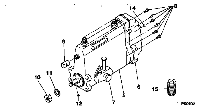
| 008. | [06] | 94904-70620 | BOLT, W/WASHER | |
| 009. | [01] | 09001-80081 | COVER, CONTROL RAC | 09001-80081 |
| 010. | [01] | 94905-03570 | NUT, HEXAGON | |
| 011. | [01] | 94901-50590 | WASHER, SPRING | |
| 012. | [1C] | 94913-00300 | KEY, WOODRUFF | |
| 012. | [1C] | 94913-00320 | KEY, WOODRUFF | |
| 012. | [1C] | 94913-00340 | KEY, WOODRUFF | |
| 012. | [1C] | 94913-00350 | KEY, WOODRUFF | |
| 014. | [01] | 90200-06511 | WASHER, PLATE | |
| 015. | [01] | 09006-10011 | COVER, PRIMING PUM | 09006-10011 |
Include in #3:
19000-05020
as PUMP ASSY, INJECTI
Cross reference number
| Part num | Firm num | Firm | Name |
| 19000-05020 | 30661-5902 | PUMP ASSY, INJECTI | |
| 30661-59020 | MITSUBISHI | PUMP ASSY, INJECTI |
Information:
1. Disconnect oil supply line (1) and oil drain tube (2). Remove the four mounting nuts and remove the turbocharger. Remove the gasket. The following steps are for the installation of the turbocharger.2. Apply 5P3931 Anti-Seize to turbocharger mounting studs. Position turbocharger gasket and turbocharger, then Install the four mounting nuts. Tighten the four mounting nuts to a torque of 54 5 N m (40 4 lb.ft.).3. Position gaskets and install drain tube (2) and supply line (1).Disassemble And Assemble Turbocharger
Start By:a. remove turbocharger 1. Remove bolts (1) and (2). Remove the compressor and turbine housings.2. Remove nut (3) and compressor wheel (4). Slide out turbine wheel (5) and shaft.3. Remove adapter plate snap ring (6).4. Use two screwdrivers and remove adapter plate (7).5. Remove bushings (8), spacers (9), and seals (10).6. Remove snap ring (11) and bushing (12).7. Remove snap ring (13) and bushing (14). The following steps are for the assembly of the turbocharger.8. Install bushing (12) and snap ring (11). Repeat for bushing (14) and snap ring (13).9. With th seals and shield (15) in place, install shaft and turbine wheel assembly (5).10. Install the spacers, bushings, plate, seals and adapter plate. Install the snap ring (not illustrated).
Do not allow any of the 7M7456 Locktite to get on the shaft. Damage to the turbocharger may occur.
11. Install compressor wheel (4) on the shaft. Put one drop of 7M7456 Locktite on the threads and install nut (3). Tighten nut (3) to a torque of 15.6 .7 N m (138 6 lb.in.).12. Position the turbine and compressor housings. Put 5P3931 Anti-Seize Compound on the bolts and install. Tighten bolts (1) for the compressor cover to a torque of 7.3 .6 N m (65 5 lb.in.). Tighten bolts (2), for the turbine housing to a torque of 15.8 .6 N m (140 5 lb.in.).End by:a. Install turbocharger