Information pump assy, injecti
Rating:
Components :
| 001. | PUMP ASSY, INJECTI | 19000-04883 |
| 002. | SWITCH KIT, CONTRO | 09009-90300 |
| 003. | BODY ASSY, INJECTI | 09010-04034 |
| 004. | COVER, BEARING | 09020-10410 |
| 005. | TIMER ASSY, AUTOMA | 09180-01210 |
| 006. | PUMP ASSY, FUEL FE | 09210-00920 |
| 007. | COUPLING ASSY | 09250-00270 |
Scheme ###:
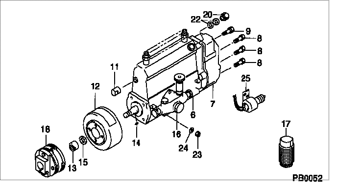
| 000. | [01] | 19000-04883 | PUMP ASSY, INJECTI | 22090-1042 |
| 006. | [01] | 09010-04034 | BODY ASSY, INJECTI | 22110-1482A |
| 007. | [01] | 09080-06461 | GOVERNOR ASSY, MEC | 22310-2051 |
| 008. | [06] | 94904-71150 | BOLT, W/WASHER | 6 306 1001 00 |
| 009. | [01] | 94904-73910 | BOLT, W/WASHER | 22815-2820A |
| 011. | [01] | 09001-80290 | COVER, CONTROL RAC | 22114-1020A |
| 012. | [01] | 09180-01210 | TIMER ASSY, AUTOMA | 22510-1190A |
| 013. | [01] | 09001-20180 | NUT, TIMER ROUND | 22511-1070A |
| 014. | [01] | 94913-00210 | KEY, WOODRUFF | 22895-1010A |
| 015. | [01] | 94901-50590 | WASHER, SPRING | 22877-1620A |
| 016. | [01] | 09210-00920 | PUMP ASSY, FUEL FE | 22570-1250A |
| 017. | [01] | 09006-10020 | COVER, PRIMING PUM | 22561-1020 |
| 018. | [01] | 09250-00270 | COUPLING ASSY | 22610-1080A |
| 020. | [01] | 09031-00130 | VALVE ASSY, OVERFL | 22107-1090A |
| 022. | [02] | 94901-02480 | WASHER | 22847-1940A |
| 023. | [03] | 90160-06051 | NUT, HEXAGON | 22825-1480A |
| 024. | [03] | 90258-06001 | WASHER, SPRING | 28219-1110A |
| 025. | [01] | 09009-90300 | SWITCH KIT, CONTRO | 22690-1200A |
Include in #3:
19000-04883
as PUMP ASSY, INJECTI
Cross reference number
| Part num | Firm num | Firm | Name |
| 19000-04883 | 22090-1042 | PUMP ASSY, INJECTI |
Information:
Remove & Install Water Pump
1. Drain the coolant from the engine into a suitable container for storage or disposal. 2. Loosen two hose clamps (1).3. Remove hose (2). 4. Remove two bolts (3).5. Remove elbow (5).6. Remove fumes disposal tube (4) for access to the water pump.7. Disconnect coolant conditioner hose (6).8. Remove heater hose (12) (previously removed).9. Loosen hose clamp (15).10. Disconnect lower radiator hose (13).11. Remove two bolts (14) from oil cooler. Check gasket for wear or damage. Replace if necessary.12. Remove four bolts (10).13. Remove water pump cover (11).14. Remove seven long bolts (7).15. Reposition air conditioning lines and oil line (8) after bolts are removed.16. Remove water pump (9). Check seals and O-rings for wear and damage before installation, replace as necessary. For installation of the water pump, reverse the removal steps.17. Fill the cooling system with coolant to correct level. See the Operation & Maintenance Manual.Disassemble Water Pump
*Part of 1P510 Driver Group.Start By:a. remove water pump The water pump seal can be replaced without removing the water pump from the engine. An intermittent leakage of a small amount of coolant from the hole in the water pump housing is not an indication of a water pump seal failure. This is required to provide lubrication for the seal. Replace the water pump seal only if a large amount of leakage or a constant flow of coolant is observed draining from the water pump housing.1. Remove O-ring seal (1) from the adapter.2. Remove adapter (2) from the housing. Remove the O-ring seal from the outside diameter of the adapter.3. Remove bolt (3) and the retainer that hold the impeller on the shaft. 4. Use Tool (A) to remove impeller (4) from the shaft. 5. Remove the spring and seal (5) from the shaft. 6. Remove four bolts (7) from retainer (6) that hold the shaft assembly to the pump housing.7. Remove O-ring seal (8) from the housing. 8. Remove gear and shaft assembly (10) from the housing.9. Remove bolt (9) and the retainer from the shaft assembly. 10. Use a press to remove the shaft assembly from gear (11). Remove the retainer from the shaft assembly. 11. Remove bearing (13), spacer (14) and bearing (12) from the shaft. 12. Remove lip-type seal (15) from the housing.13. Turn the housing over, and remove ceramic ring (16) and the seal.Assemble Water Pump
1. Use 6V1541 Quick Cure Primer to clean shaft (8) and the seal counterbore in the pump housing.2. Install bearing (4), spacer (3) and bearing (2) on shaft (8).3. Put retainer (1) and gear (7) in position on the shaft assembly. Install retainer (6) and bolt (5). 4. Use Tool (A) to install the lip-type seal in the housing as shown. Put a small amount of clean SAE 30 Oil on the lip of the seal. 5. Install a new O-ring seal (10) on the housing.6. Put shaft assembly (9) in position in the housing. Install the bolts that hold the retainer to the housing.
Clean water