Information pump assy, injecti
Rating:
KIT List:
| Body assy, injecti | 1904400430 |
| Governor assy, mec | NO APPLICATION |
| Pump assy, fuel fe | 1922900070 |
Components :
| 001. | PUMP ASSY, INJECTI | 19000-04570 |
| 002. | BODY ASSY, INJECTI | 09010-04310 |
| 003. | COVER, BEARING | 09020-10110 |
| 004. | GOVERNOR ASSY, MEC | 09080-06310 |
| 005. | PUMP ASSY, FUEL FE | 09210-01220 |
Scheme ###:
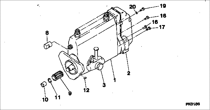
| 000. | [01] | 19000-04570 | PUMP ASSY, INJECTI | 2158134KZ |
| 001. | [01] | 09010-04310 | BODY ASSY, INJECTI | |
| 002. | [01] | 09080-06310 | GOVERNOR ASSY, MEC | |
| 003. | [01] | 09210-01220 | PUMP ASSY, FUEL FE | |
| 004. | [01] | 09255-10300 | BLOCK, COUPLING | |
| 009. | [01] | 09001-80152 | COVER, CONTROL RAC | |
| 010. | [01] | 09002-60050 | SCREW, ADJUSTING | |
| 011. | [01] | 94805-30100 | NUT, HEXAGON, W/HO | |
| 012. | [02] | 94901-80350 | WASHER, COPPER PLA | |
| 013. | [01] | 09003-20040 | CAP | |
| 014. | [01] | 94901-80710 | WASHER, COPPER PLA | |
| 015. | [08] | 91418-06201 | BOLT, W/WASHER | |
| 015. | [08] | 91518-06201 | BOLT, W/WASHER | |
| 016. | [01] | 94905-03400 | NUT, HEXAGON | |
| 017. | [01] | 94901-40070 | WASHER, COUNTERSUN | |
| 018. | [01] | 90458-05750 | KEY, WOODRUFF |
Include in #3:
19000-04570
as PUMP ASSY, INJECTI
Cross reference number
| Part num | Firm num | Firm | Name |
| 19000-04570 | 2158134KZ | PUMP ASSY, INJECTI | |
| 2158134KZ | OTHERS | PUMP ASSY, INJECTI |
Information:
Keep all parts clean from contaminants. Contaminants put into the system may cause rapid wear and shortened component life.
1. Turn the crankshaft until the "C" mark on the crankshaft gear is in alignment with the "C" mark on the camshaft gear. To keep the engine timing correct during removal and installation of the camshaft, put a mark on the teeth of the fuel injection pump drive gear and idler gear at location (A). Put a mark on the teeth of the idler gear and camshaft gear at location (B). When installing the camshaft, the engine timing will be correct when the marks at locations (A) and (B) are in alignment and the "C" marks on the crankshaft and camshaft gears are in alignment.2. Remove the bolts, lock and washer (1) that hold the camshaft in position.
Do not cause damage to the lobes or bearings when the camshaft is removed.
3. Remove the camshaft and gear (2).4. If necessary, remove the bolts and gear. The following steps are for the installation of the camshaft.5. Put the camshaft drive gear in position on the end of the camshaft, and install the bolts that hold it. Tighten the bolts to a torque of 55 7 N m (41 5 lb ft).
Do not cause damage to the lobes or bearings when the camshaft is installed.
6. Put 2P2506 Thread Lubricant on the camshaft lobes only, and clean engine oil on the bearing journals. Install camshaft (3) aligning the "C" marks and the marks put on the gears during removal.7. Install washer (1), the lock and bolts.End By:a. install valve liftersb. install timing gear cover
Perform Scheduled Oil Sampling on oil wetted compartments after performing service work to check for contaminants left in the system following repair. Contaminants put into the system may cause rapid wear and shortened component life.