Information pump assy, injecti
Rating:
Components :
| 001. | PUMP ASSY, INJECTI | 19000-04561 |
| 002. | BODY ASSY, INJECTI | 09010-03861 |
| 003. | TIMER ASSY, AUTOMA | 09180-01170 |
| 004. | PUMP ASSY, FUEL FE | 09210-00920 |
| 005. | COUPLING ASSY | 09250-00270 |
Scheme ###:
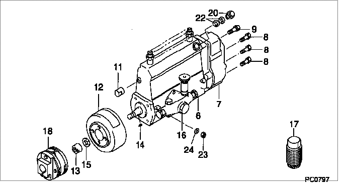
| 000. | [01] | 19000-04561 | PUMP ASSY, INJECTI | 22030-1210 |
| 006. | [01] | 09010-03861 | BODY ASSY, INJECTI | 22130-1060A |
| 007. | [01] | 09080-06740 | GOVERNOR ASSY, MEC | |
| 008. | [06] | 94900-50191 | SCREW, SLOTTED FLA | 6 056 1305 60 |
| 009. | [01] | 91518-08221 | BOLT, W/WASHER | 22815-1190A |
| 011. | [01] | 09001-80290 | COVER, CONTROL RAC | 22114-1020A |
| 012. | [01] | 09180-01170 | TIMER ASSY, AUTOMA | 22510-1160A |
| 013. | [01] | 09001-20180 | NUT, TIMER ROUND | 22511-1070A |
| 014. | [01] | 94913-00210 | KEY, WOODRUFF | 22895-1010A |
| 015. | [01] | 94901-50590 | WASHER, SPRING | 22877-1620A |
| 016. | [01] | 09210-00920 | PUMP ASSY, FUEL FE | 22570-1250A |
| 017. | [01] | 09006-10011 | COVER, PRIMING PUM | 6 053 1552 60 |
| 018. | [01] | 09250-00270 | COUPLING ASSY | 22610-1080A |
| 020. | [01] | 09031-00130 | VALVE ASSY, OVERFL | 22107-1090A |
| 022. | [02] | 94901-02480 | WASHER | 22847-1940A |
| 023. | [03] | 90160-06051 | NUT, HEXAGON | 22825-1480A |
| 024. | [03] | 90258-06001 | WASHER, SPRING | 28219-1110A |
Include in #3:
19000-04561
as PUMP ASSY, INJECTI
Cross reference number
| Part num | Firm num | Firm | Name |
| 19000-04561 | 22030-1210 | PUMP ASSY, INJECTI |
Information:
Start By:a. remove timing gear cover 1. Remove bolt (1) and washer that fastens the weight assembly (2).
Weight assembly must have support during removal to prevent damage to components.
2. Install tooling (A) and remove the weight assembly.Install Automatic Timing Advance Unit
1. Install washer and bolt (1). With the fuel pump housing cover removed, turn the fuel pump camshaft in the direction of engine rotation until tool (A) can be installed in the notch of the camshaft. 2. To time the fuel injection pump to the engine with the front timing cover removed, follow Steps 3 and 4. With the timing cover installed, see Steps 6 and 7. No. 1 piston at top center (TC) on the compression stroke is the starting point for all timing procedures. The engine is seen from the flywheel end when direction of crankshaft rotation is given.3. Turn the crankshaft counterclockwise until the "C" on the crankshaft and camshaft and camshaft gears are in alignment. 4. Remove the plug and install tool (B) in the flywheel housing.5. To find top center compression stroke for No. 1 piston, turn the flywheel clockwise (opposite of engine rotation) approximately 30°. This procedure is to remove all end play from timing gears.6. Turn the flywheel counterclockwise (direction of engine rotation) until tool (B) can be installed in the flywheel. The piston is at top center. If you go past the bolt hole you must start over again. To see if the No. 1 piston is on the compression stroke, remove the breather assembly from the valve cover and look at the valves of the No. 1 cylinder. The valves will be closed if No. 1 cylinder is on the compression stroke. You must be able to move the rocker arms up and down with your hand.7. If NO. 1 piston is not on the compression stroke, remove tooling (B) and turn the flywheel 360° counterclockwise. Install tooling (B). The No. 1 piston is now at top center on the compression stroke.8. With tooling (A) and (B) installed in position, install the timing advance weight assembly on the fuel pump camshaft. 9. Install tooling (C) on the weight assembly. While a constant torque on drive gear on 68 N m (50 lb ft) is held, tighten the bolt that fastens the weight assembly to fuel pump camshaft to a torque of 270 25 N m (200 18 lb ft).10. Remove tooling (A), (B) and (C).End By:a. install timing gear coverDisassemble And Assemble Automatic Timing Unit
Start By:a. remove automatic timing advance unit
Keep all parts clean from contaminants. Contaminants put into the system may cause rapid wear and shortened component life.
1. Remove two screws (1) and plate (2).
The weights are held on position with two springs for each weight under compression. Carefully remove weights and springs to prevent possible injury.
2. Remove springs (4) and (5), weight (3) and slide (6) from each side of assembly. 3. If necessary, remove gear (7). Remove seals (11) and (10). The following steps