Information pump assy, injecti
Rating:
Components :
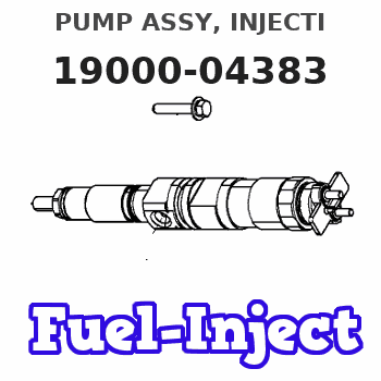
| 001. | PUMP ASSY, INJECTI | 19000-04383 |
| 002. | BODY ASSY, INJECTI | 09010-04201 |
| 003. | GOVERNOR ASSY, MEC | 09080-07491 |
| 004. | PUMP ASSY, FUEL FE | 09210-01440 |
Scheme ###:
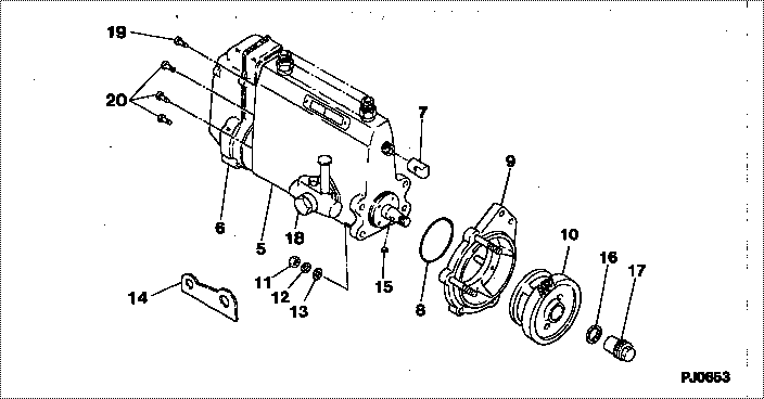
| 000. | [01] | 19000-04383 | PUMP ASSY, INJECTI | ME039614 |
| 005. | [01] | 09010-04201 | BODY ASSY, INJECTI | ME703510 |
| 006. | [01] | 09080-07491 | GOVERNOR ASSY, MEC | ME027337 |
| 007. | [01] | 09001-80081 | COVER, CONTROL RAC | ME702034 |
| 008. | [01] | 94914-02840 | O-RING | MH035502 |
| 009. | [01] | 09006-00050 | COVER SUB-ASSY, TI | ME036902 |
| 010. | [01] | 09185-10280 | GEAR, TIMER DRIVIN | ME039744 |
| 011. | [04] | 91266-10081 | NUT, HEXAGON | MF430122 |
| 012. | [04] | 90258-10001 | WASHER, SPRING | MC327716 |
| 013. | [04] | 94901-15020 | WASHER, STEEL PLAT | MH005068 |
| 014. | [01] | 09009-20100 | BRACKET | ME702036 |
| 015. | [01] | 94913-00210 | KEY, WOODRUFF | ME702047 |
| 016. | [01] | 94901-40210 | WASHER, COUNTERSUN | ME702043 |
| 017. | [01] | 09001-20220 | NUT, TIMER ROUND | ME702033 |
| 018. | [01] | 09210-01440 | PUMP ASSY, FUEL FE | ME035928 |
| 019. | [01] | 91518-08221 | BOLT, W/WASHER | MM500963 |
| 020. | [06] | 91418-06161 | BOLT, W/WASHER | ME702149 |
Include in #3:
19000-04383
as PUMP ASSY, INJECTI
Cross reference number
| Part num | Firm num | Firm | Name |
| 19000-04383 | ME039614 | PUMP ASSY, INJECTI |
Information:
Keep all parts clean from contaminants. Contaminants put into the system may cause rapid wear and shortened component life.
1. Put compression on valve spring (2) with tool (A), and remove locks (1).2. Remove tool (A), rotocoil, spring, valve stem oil shield and valve. Put identification marks on valves with respect to their location in the cylinder head. 3. Check the spring force with tool (B). The spring force is 257 25 N (57.8 5.6 lb.). The length of spring under test force is 44.86 mm (1.766 in). The free length after test is 52.07 mm (2.050 in).4. Perform Steps 1 through 3 again for the remainder of the valves. The following steps are for the installation of the valves.5. Put clean engine oil on the valve stems. Install the valve, oil shield, spring (2) and rotocoil in the cylinder head. 6. Put tool (A) in position on the valve spring, and install the locks with tool (C).
Locks can be thrown from valve when the compressor is released if they are not in their correct position on valve stem. Personal injury can be the result if not carefully removed.
7. Remove tool (A), and hit the top of valve with a plastic hammer be sure the locks are in their correct position on valve.8. Do Steps 5 through 7 again for the remainder of the valves.End By:a. install spacer plate