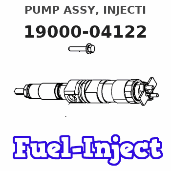
Information pump assy, injecti
Rating:
Components :
| 001. | PUMP ASSY, INJECTI | 19000-04122 |
| 002. | SWITCH KIT, CONTRO | 09009-90230 |
| 003. | BODY ASSY, INJECTI | 09010-03922 |
| 004. | COVER, BEARING | 09020-10410 |
| 005. | GOVERNOR ASSY, MEC | 09080-06100 |
| 006. | TIMER ASSY, AUTOMA | 09180-01210 |
| 007. | PUMP ASSY, FUEL FE | 09210-00920 |
| 008. | COUPLING ASSY | 09250-00270 |
Scheme ###:
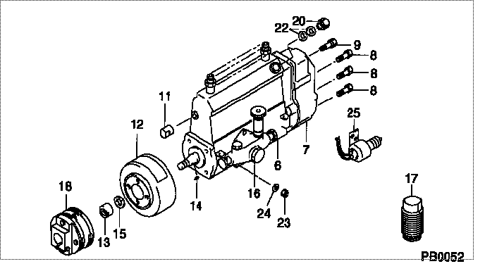
| 000. | [01] | 19000-04122 | PUMP ASSY, INJECTI | 22010-2401 |
| 006. | [01] | 09010-03922 | BODY ASSY, INJECTI | 22110-1590A |
| 007. | [01] | 09080-06100 | GOVERNOR ASSY, MEC | 22310-1560 |
| 008. | [06] | 94904-71150 | BOLT, W/WASHER | 6 306 1001 00 |
| 009. | [01] | 94904-73910 | BOLT, W/WASHER | 22815-2820A |
| 011. | [01] | 09001-80290 | COVER, CONTROL RAC | 22114-1020A |
| 012. | [01] | 09180-01210 | TIMER ASSY, AUTOMA | 22510-1190A |
| 013. | [01] | 09001-20180 | NUT, TIMER ROUND | 22511-1070A |
| 014. | [01] | 94913-00210 | KEY, WOODRUFF | 22895-1010A |
| 015. | [01] | 94901-50590 | WASHER, SPRING | 22877-1620A |
| 016. | [01] | 09210-00920 | PUMP ASSY, FUEL FE | 22570-1250A |
| 017. | [01] | 09006-10011 | COVER, PRIMING PUM | 6 053 1552 60 |
| 018. | [01] | 09250-00270 | COUPLING ASSY | 22610-1080A |
| 020. | [01] | 09031-00130 | VALVE ASSY, OVERFL | 22107-1090A |
| 022. | [02] | 94901-02480 | WASHER | 22847-1940A |
| 023. | [03] | 90160-06051 | NUT, HEXAGON | 22825-1480A |
| 024. | [03] | 90258-06001 | WASHER, SPRING | 28219-1110A |
| 025. | [01] | 09009-90230 | SWITCH KIT, CONTRO | 22690-1120 |
Include in #3:
19000-04122
as PUMP ASSY, INJECTI
Cross reference number
| Part num | Firm num | Firm | Name |
| 19000-04122 | 22010-2401 | PUMP ASSY, INJECTI |
Information:
Keep all parts clean from contaminants. Contaminants put into the system may cause rapid wear and shortened component life.
1. Remove idler gear (7).2. Remove the gear train housing, which has the Power Take Off, (PTO), mounted to it.3. Remove bolts (3) and drive opening cover (10). Remove PTO gear assembly (1). Remove six nuts (4).4. Remove adapter assembly (2) and o-ring seals (6) and (8).5. If necessary, remove bearing sleeves (9) and (5) for the idler gear and the PTO gear (1). Make note of the positioning of the oil holes in the bearings. Proper location of the holes during installation is necessary for lubrication. The following steps are for the installation of the PTO Assembly.6. Install bearing sleeves (5) and (9). Be sure to align oil holes.7. Install PTO assembly in the gear train housing. Coat the bearing sleeves with clean engine oil. Install o-ring seal (8). Position adapter assembly (2) on the studs and install the nuts8. Install o-ring seal (6), drive opening cover (10) and bolts (3).9. Install the gear train housing on the engine block.10. Install the idler gear. Apply 5P3414 Pipe Sealant to the threads of the bolts and install. Torque to 135 15 N m (100 11 lb ft).
Perform Scheduled Oil Sampling on oil wetted compartments after performing service work to check for contaminants left in the system following repair. Contaminants put into the system may cause rapid wear and shortened component life.
End By:a. install flywheel housing