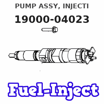
Information pump assy, injecti
Rating:
Components :
| 001. | PUMP ASSY, INJECTI | 19000-04023 |
| 002. | BODY ASSY, INJECTI | 09010-04200 |
| 003. | BODY ASSY, INJECTI | 09010-04511 |
| 004. | GOVERNOR ASSY, MEC | 09080-06040 |
| 005. | GOVERNOR ASSY, MEC | 09080-06611 |
| 006. | TIMER ASSY, AUTOMA | 09180-01240 |
| 006. | TIMER ASSY, AUTOMA | 09180-01240 |
| 007. | PUMP ASSY, FUEL FE | 09210-01270 |
| 008. | PUMP ASSY, FUEL FE | 09210-01391 |
Scheme ###:
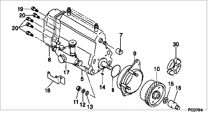
| 000. | [01] | 19000-04023 | PUMP ASSY, INJECTI | ME038809 |
| 005. | [01] | 09010-04200 | BODY ASSY, INJECTI | ME703510 |
| 005. | [01] | 09010-04511 | BODY ASSY, INJECTI | ME039652 |
| 006. | [01] | 09080-06040 | GOVERNOR ASSY, MEC | ME039628 |
| 006. | [01] | 09080-06611 | GOVERNOR ASSY, MEC | |
| 007. | [01] | 09001-80081 | COVER, CONTROL RAC | ME702034 |
| 008. | [01] | 94914-02840 | O-RING | MH035502 |
| 009. | [01] | 09006-00071 | COVER SUB-ASSY, TI | ME039698 |
| 010. | [01] | 09180-01240 | TIMER ASSY, AUTOMA | 31860-81050 |
| 011. | [04] | 91266-10081 | NUT, HEXAGON | MF430122 |
| 012. | [04] | 90258-10001 | WASHER, SPRING | MC327716 |
| 013. | [04] | 94901-15020 | WASHER, STEEL PLAT | MH005068 |
| 014. | [01] | 94913-00210 | KEY, WOODRUFF | ME702047 |
| 015. | [01] | 94901-40210 | WASHER, COUNTERSUN | ME702043 |
| 016. | [01] | 09001-20220 | NUT, TIMER ROUND | ME702033 |
| 017. | [01] | 09210-01391 | PUMP ASSY, FUEL FE | ME039653 |
| 017. | [01] | 09210-01270 | PUMP ASSY, FUEL FE | ME039699 |
| 018. | [01] | 09009-20100 | BRACKET | ME702036 |
| 019. | [01] | 91518-08221 | BOLT, W/WASHER | MM500963 |
| 020. | [06] | 91418-06161 | BOLT, W/WASHER | ME702149 |
| 030. | [01] | 09243-60180 | COUPLING, INJECTIO | 31860-90300 |
Include in #3:
19000-04023
as PUMP ASSY, INJECTI
Cross reference number
| Part num | Firm num | Firm | Name |
| 19000-04023 | ME038809 | PUMP ASSY, INJECTI |
Information:
Keep all parts clean from contaminants. Contaminants put into the system may cause rapid wear and shortened component life.
1. Unplug the connector and remove speed pickup (1) to prevent damage to the unit.2. Install tool (A) on the flywheel as shown and fasten a hoist.3. Remove bolts (2) and flywheel (3). The weight of the flywheel is 72 kg (160 lb.).4. If necessary, remove the ring gear from the flywheel with a hammer and punch. The following steps are for the installation of the flywheel.
The ring gear must be installed with the chamfered side of the teeth up as shown in the inset of illustration A89844P2. This will put the chamfered side of the gear teeth toward the starter when the flywheel is installed so the starter will engage correctly.
1. Heat ring gear (4) to a maximum temperature of 320° C (608° F). Install the ring gear. 2. Install tooling (A) on the flywheel in the same position it was during removal. Install two 5/8" - 18 NF guide bolts in the crankshaft if necessary.3. Make an alignment of timing mark (5) on the crankshaft and timing mark (6) on the flywheel. Hold flywheel (3) in position and install bolts (2). Tighten bolts (2) to a torque of 205 27 N m (151 20 lb ft).4. Remove tool (A).5. Install speed pickup (1). Hand tighten speed pickup (1) until it makes contact with the flywheel. Loosen speed pickup (1) one half turn (180°) after contacting the flywheel. Tighten the locknut on speed pickup (1) and the connect wiring harness.End By:a. install engine