Information pump assy, injecti
PUMP ASSY, INJECTI
GA
- THE ELEMENT, TIMER AND THE NOZZLE ARE DIFFERENT
- COMPARING WITH 190000-1372.
Nozzle:
0935002010
Rating:
KIT List:
| Body assy, injecti | 1904400300 |
| Governor assy, inj | 1908900260 |
| Timer assy, automa | 0918030050 |
| Pump assy, fuel fe | 1922900060 |
Components :
| 001. | PUMP ASSY, INJECTI | 19000-03640 |
| 001. | PUMP ASSY, INJECTI | 19000-03640 |
| 002. | BODY ASSY, INJECTI | 09010-04060 |
| 002. | BODY ASSY, INJECTI | 09010-04060 |
| 003. | TIMER ASSY, AUTOMA | 09180-01260 |
| 003. | TIMER ASSY, AUTOMA | 09180-01260 |
| 004. | PUMP ASSY, FUEL FE | 09210-01071 |
| 004. | PUMP ASSY, FUEL FE | 09210-01071 |
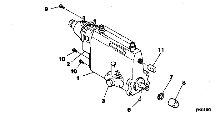
Scheme ###:
| 000. | [01] | 19000-03640 | PUMP ASSY, INJECTI | 22100-87346-000 |
| 000. | [01] | 19000-03640 | PUMP ASSY, INJECTI | 2210A-87346 |
| 001. | [01] | 09010-04060 | BODY ASSY, INJECTI | 2212A-87307 |
| 001. | [01] | 09010-04060 | BODY ASSY, INJECTI | 22120-87307-000 |
| 002. | [01] | 09050-00901 | GOVERNOR ASSY, INJ | 2231A-87306 |
| 002. | [01] | 09050-00901 | GOVERNOR ASSY, INJ | 22310-87306-000 |
| 003. | [01] | 09210-01071 | PUMP ASSY, FUEL FE | 2251A-87303 |
| 003. | [01] | 09210-01071 | PUMP ASSY, FUEL FE | 22510-87308-000 |
| 006. | [01] | 94913-00190 | KEY, WOODRUFF | |
| 006. | [01] | 94913-00190 | KEY, WOODRUFF | 90099-13002-000 |
| 007. | [01] | 94901-50500 | WASHER, SPRING | 22877-1540A |
| 007. | [01] | 94901-50500 | WASHER, SPRING | 22173-87301-000 |
| 008. | [01] | 09001-20260 | NUT, TIMER ROUND | |
| 008. | [01] | 09001-20260 | NUT, TIMER ROUND | 22611-68010-000 |
| 009. | [01] | 91518-08221 | BOLT, W/WASHER | 90091-20804-000 |
| 009. | [01] | 91518-08221 | BOLT, W/WASHER | 22815-1190A |
| 010. | [04] | 91518-06161 | BOLT, W/WASHER | 22128-87702-000 |
| 010. | [04] | 91518-06161 | BOLT, W/WASHER | 22815-1310A |
| 011. | [01] | 09001-80010 | COVER, CONTROL RAC | 22116-77020-000 |
| 011. | [01] | 09001-80010 | COVER, CONTROL RAC | 22118-1120 |
| 100. | [01] | 09180-01260 | TIMER ASSY, AUTOMA | 22610-87307-000 |
| 100. | [01] | 09180-01260 | TIMER ASSY, AUTOMA | 2261A-87307 |
Include in #3:
19000-03640
as PUMP ASSY, INJECTI
19000-03640
Cross reference number
| Part num | Firm num | Firm | Name |
| 19000-03640 | 22100-8734 | PUMP ASSY, INJECTI | |
| 2210A-87346 | HINO | PUMP ASSY, INJECTI | |
| 22100-87346-000 | DAIHATSU | PUMP ASSY, INJECTI |
Information:
Remove Aftercooler Core
1. Drain the coolant from the cooling system to a level below the aftercooler. 2. Remove three nuts and washers (1).3. Move Peec unit (2) out of the way. (If so equipped). 4. Remove elbows (5) and pipes (7).5. Remove fuel line brackets (4).6. Remove bolts (6). Remove cover (3). 7. Remove elbows (10). Remove adapters (8) and adapters (9) from the aftercooler core. Remove bolts (11). 8. Move aftercooler core (12) toward the front of the engine and use two people to remove the aftercooler core from the lower aftercooler housing. The weight of the aftercooler core is approximately 29 kg (65 lb). Remove the O-ring seals from the aftercooler core extensions.Install Aftercooler
1. Install O-ring seals (13) on the aftercooler core extensions. Put clean engine oil or glycerin on the seals.2. Use two people to put aftercooler core (12) into position in the lower aftercooler housing. The weight of the aftercooler core is approximately 29 kg (65 lb). 3. Install bolts (11). Put clean engine oil or glycerin on O-ring seal (14) and in bores (15) and (16). 4. Put clean engine oil or glycerin on O-ring seals (17) and adapters (8) and (9). Install adapters (8) and (9) in the aftercooler core. 5. Install elbows (10). 6. Put cover (3) into position on the engine. Install bolts (6).7. Install fuel injection line brackets (4). Tighten bolts (20) to a torque of 4.5 1.1 N m (40 10 lb in).8. Put clean engine oil or glycerin on pipes (7). Install pipes (7) and elbows (5).9. Fill the cooling system with coolant. See Operation & Maintenance Manual for the proper procedure and levels.