Information pump assy, injecti
Nozzle:
0935001820
Rating:
KIT List:
| Body assy, injecti | 1904400340 |
| Governor assy, mec | 1908900190 |
| Timer assy, automa | 0918030060 |
| Pump assy, fuel fe | 1922900060 |
Components :
| 001. | PUMP ASSY, INJECTI | 19000-03600 |
| 001. | PUMP ASSY, INJECTI | 19000-03600 |
| 002. | BODY ASSY, INJECTI | 09010-09780 |
| 002. | BODY ASSY, INJECTI | 09010-09780 |
| 003. | GOVERNOR ASSY, MEC | 09080-04990 |
| 003. | GOVERNOR ASSY, MEC | 09080-04990 |
| 004. | TIMER ASSY, AUTOMA | 09180-01001 |
| 004. | TIMER ASSY, AUTOMA | 09180-01001 |
| 005. | PUMP ASSY, FUEL FE | 09210-01450 |
| 005. | PUMP ASSY, FUEL FE | 09210-01450 |
| 005. | PUMP ASSY, FUEL FE | 09210-01450 |
| 005. | PUMP ASSY, FUEL FE | 09210-01450 |
| 006. | COUPLING ASSY | 09240-00161 |
| 006. | COUPLING ASSY | 09240-00161 |
Scheme ###:
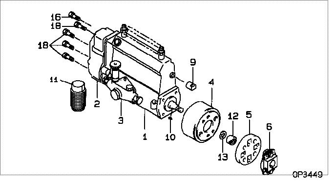
| 000. | [01] | 19000-03600 | PUMP ASSY, INJECTI | 22100-31632-71 |
| 000. | [01] | 19000-03600 | PUMP ASSY, INJECTI | 22100-31632-71 |
| 001. | [01] | 09010-09780 | BODY ASSY, INJECTI | |
| 001. | [01] | 09010-09780 | BODY ASSY, INJECTI | |
| 002. | [01] | 09080-04990 | GOVERNOR ASSY, MEC | 22410-31630-71 |
| 002. | [01] | 09080-04990 | GOVERNOR ASSY, MEC | 22410-31630-71 |
| 003. | [01] | 09210-01450 | PUMP ASSY, FUEL FE | |
| 003. | [01] | 09210-01450 | PUMP ASSY, FUEL FE | |
| 004. | [01] | 09180-01001 | TIMER ASSY, AUTOMA | 22610-77040 |
| 004. | [01] | 09180-01001 | TIMER ASSY, AUTOMA | |
| 005. | [01] | 09243-60020 | COUPLING, INJECTIO | 22632-66010 |
| 005. | [01] | 09243-60020 | COUPLING, INJECTIO | |
| 006. | [01] | 09240-00161 | COUPLING ASSY | 22630-77051 |
| 006. | [01] | 09240-00161 | COUPLING ASSY | |
| 009. | [01] | 09001-80010 | COVER, CONTROL RAC | 22116-77020 |
| 009. | [01] | 09001-80010 | COVER, CONTROL RAC | |
| 010. | [01] | 94913-00050 | KEY, WOODRUFF | 90099-13002 |
| 010. | [01] | 94913-00050 | KEY, WOODRUFF | 90099-13002 |
| 011. | [01] | 09006-10011 | COVER, PRIMING PUM | |
| 011. | [01] | 09006-10011 | COVER, PRIMING PUM | 22511-77020 |
| 012. | [01] | 09001-20010 | NUT, TIMER ROUND | |
| 012. | [01] | 09001-20010 | NUT, TIMER ROUND | 22611-77020 |
| 013. | [01] | 90258-12001 | WASHER, SPRING | |
| 013. | [01] | 90258-12001 | WASHER, SPRING | 94511-01200 |
| 016. | [01] | 94904-73910 | BOLT, W/WASHER | |
| 016. | [01] | 94904-73910 | BOLT, W/WASHER | 90099-04346 |
| 018. | [06] | 94904-70620 | BOLT, W/WASHER | |
| 018. | [06] | 94904-70620 | BOLT, W/WASHER | 90099-04526 |
Include in #3:
19000-03600
as PUMP ASSY, INJECTI
19000-03600
Cross reference number
| Part num | Firm num | Firm | Name |
| 19000-03600 | 22100-3163 | PUMP ASSY, INJECTI | |
| 22100-31632-71 | TOYOTA | PUMP ASSY, INJECTI | |
| 22100-31632-71 | TICO | PUMP ASSY, INJECTI |
Information:
Remove & Install Fuel Transfer Pump
1. Disconnect fuel lines (1) from fuel transfer pump (3). Remove bolts (2). Remove fuel transfer pump (3). Remove gasket from fuel transfer pump.2. Install a new gasket on fuel transfer pump (3). Install fuel transfer pump on rear plate with the bolts (2) that hold it. Connect fuel lines (1) to the fuel transfer pump.Disassemble Fuel Transfer Pump
Start By:a. remove fuel transfer pump 1. Remove tachometer drive (3) from transfer pump cover (4).2. Remove bolts (1). Make a separation between cover (4) and pump body (2). 3. Remove lip-type seal (6) from the cover. Remove plug (5), seal, spring and plunger (bypass valve) from the cover. 4. Remove nut (10) from shaft (7). Remove gear (9) and key (11).5. Remove shaft (7) and gear (8) as a unit. Remove gear (8) from drive shaft (7) with a press.6. Remove idler gear (12). 7. Remove bushing (14), two lip-type seals and the bottom bearing from pump body (1).8. Remove check valve (13). Assemble Fuel Transfer Pump
1. Install bushing (4) in body (3) with Tooling (B). The bushing must not be extended above the (gear) surface of the body.2. Install the check valve in the body with Tooling (A).3. Install lip-type seal (5) with Tooling (C). Install the seal until it is 24.6 0.5 mm (97 .02) from the bottom surface of body (3) and with the lip toward bushing (4) as shown.4. Install lip-type seal (6) with Tooling (D). Install the seal until it is 14.2 0.5 mm (.56 .02 in) from the bottom surface of body (3) and with the lip away from seal (5) as shown.5. Install bearing (7) in body (3) with Tooling (E). The bearing must be even with the surface of the pump body. 6. Heat gear (8) to a maximum temperature of 316°C (600°F). Install gear (8) on shaft (11) until dimension (X) is 49.71 0.25 mm (1.957 0.10 in).7. Install the drive shaft and gear in body (3). Install key, gear (10) and nut (9). Tighten the nut to a torque of 28 7 N m (22 5 lb ft).8. Install idler gear (12) in body (3).9. Install lip-type seal (2) with Tooling (C). Install the seal until it is 3.8 0.5 mm (.15 .02 in) from the top surface of cover (1) with the lip toward the inside as shown. 10. Install plunger (14) (bypass valve), spring (15), seal plug (13) in pump cover (1). Tighten plug (13) to a torque of 28 4 N m (27 3 lb ft).11. Put 7M-7260 Liquid Gasket Material on the surface of cover (1). Install cover (1) on pump body.
Do not let the liquid gasket enter the pump.
The drive shaft must turn freely after the bolts that hold the transfer pump together are tightened.12. Install tachometer drive on transfer pump cover (1).End By:a. install fuel transfer pump