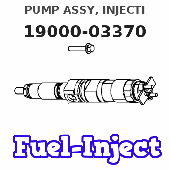
Information pump assy, injecti
Nozzle:
0935000800
Rating:
Components :
| 001. | PUMP ASSY, INJECTI | 19000-03370 |
| 002. | BODY ASSY, INJECTI | 09010-03270 |
| 003. | COVER, BEARING | 09020-10053 |
| 004. | TIMER ASSY, AUTOMA | 09180-01221 |
| 005. | PUMP ASSY, FUEL FE | 09210-00441 |
| 006. | COUPLING ASSY | 09240-00043 |
Scheme ###:
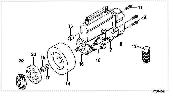
| 000. | [01] | 19000-03370 | PUMP ASSY, INJECTI | 22010-2150 |
| 007. | [01] | 09010-03270 | BODY ASSY, INJECTI | 22110-1160A |
| 008. | [01] | 09080-05710 | GOVERNOR ASSY, MEC | 22310-1430 |
| 009. | [06] | 94904-71150 | BOLT, W/WASHER | 6 306 1001 00 |
| 011. | [01] | 94904-73910 | BOLT, W/WASHER | 22815-2820A |
| 013. | [01] | 09001-80120 | COVER, CONTROL RAC | 22371-1170A |
| 014. | [01] | 09180-01221 | TIMER ASSY, AUTOMA | 22510-1220A |
| 015. | [01] | 09001-20010 | NUT, TIMER ROUND | 22353-1050A |
| 016. | [01] | 94913-00050 | KEY, WOODRUFF | 22891-1040A |
| 017. | [01] | 90258-12001 | WASHER, SPRING | 22873-1310A |
| 018. | [01] | 09210-00441 | PUMP ASSY, FUEL FE | 22570-1161A |
| 019. | [01] | 09006-10020 | COVER, PRIMING PUM | 22561-1020 |
| 022. | [01] | 09240-00043 | COUPLING ASSY | 22610-1090A |
| 023. | [01] | 09243-60020 | COUPLING, INJECTIO | 22612-1020A |
Include in #3:
19000-03370
as PUMP ASSY, INJECTI
Cross reference number
| Part num | Firm num | Firm | Name |
| 19000-03370 | 22010-2150 | PUMP ASSY, INJECTI | |
| 22010-2150 | HINO | PUMP ASSY, INJECTI |
Information:
Remove Crankshaft
Start By:a. remove oil pumpb. remove timing gear coverc. remove flywheel housingd. remove pistons For more detail about removal of main bearings, see the topic "Remove & Install Crankshaft Main Bearings" in this module. 1. Check each bearing cap (1) for its location on the engine. Each cap has an arrow which is toward the front of the block and a number which gives the location of that cap. Keep each bearing with the correct cap.2. Remove bearing caps No. 2 through No. 6. Remove thrust plates from No. 4 upper bearing.3. Install one of the flywheel bolts in each end of the crankshaft. Fasten a hoist to the crankshaft as shown. Remove No. 1 and No. 7 main bearing caps. Remove the crankshaft. Weight of the crankshaft is 181 kg (400 lb).
Be careful not to damage the crankshaft journals when the crankshaft is removed.
4. Remove crankshaft gear (2) with Tooling (A).5. Remove dowel and pin from crankshaft with Tooling (B).Install Crankshaft
1. Install pin (1) in the crankshaft end until it is extended from the surface a distance of 6.4 0.5 mm (.25 .02 in).2. Install dowel (2) until it is extended from the surface a distance of 4.1 0.5 mm (.16 .02 in). 3. Heat crankshaft gear (3) to a maximum temperature of 232°C (450°F). Install gear (3) on the crankshaft with groove (4) in alignment with dowel (2).4. Make sure the upper main bearings are clean. Put clean oil on the upper main bearings and journals of the crankshaft. 5. Install one of the flywheel bolts in each end of the crankshaft. Fasten a hoist to the crankshaft and put it in position in the block.
Use care to prevent damage to the crankshaft journals. Make sure the "V" mark on the crankshaft gear is in alignment with the "V" mark on the idler gear.
For more detail about installation of main bearings, see Remove And Install Crankshaft Main Bearings.6. Check the bearing clearances with Plastigage.7. Put clean engine oil on the bolts for caps No. 1 and No. 7. Install No. 1 and No. 7 caps with the bolts finger tight. Make sure the arrows on the caps are toward the front of the block. 8. Install thrust plates (5) for the No. 4 upper main bearing. Install the thrust plates with the side that has identification "BLOCK SIDE" toward the cylinder block.9. Put clean oil on the bolts for caps No. 2 through No. 6. Install caps No. 2 through No. 6 with the bolts finger tight. Make sure the arrows are toward the front of the block.
Do not use an impact wrench to tighten the bolts the additional 120 degrees.
10. Tighten the cap bolts as follows:a. Tighten the bolts on the tab end of the caps first to a torque of 260 14 N m