Information pump assy, injecti
Nozzle:
0935000800
Rating:
Components :
| 001. | PUMP ASSY, INJECTI | 19000-03310 |
| 002. | BODY ASSY, INJECTI | 09010-03260 |
| 003. | COVER, BEARING | 09020-10053 |
| 004. | TIMER ASSY, AUTOMA | 09180-01221 |
| 005. | PUMP ASSY, FUEL FE | 09210-00342 |
| 006. | COUPLING ASSY | 09240-00043 |
Scheme ###:
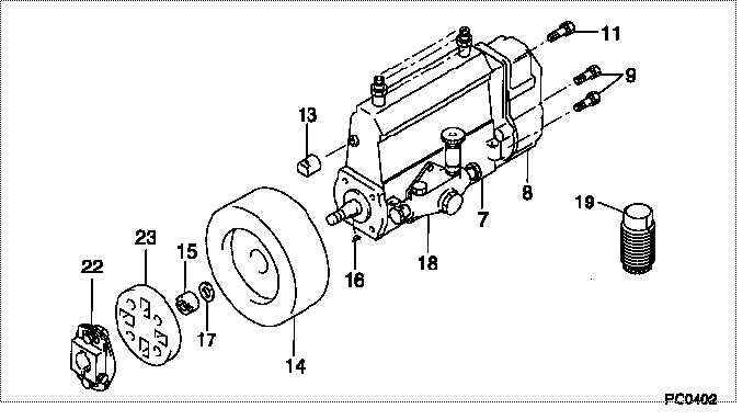
| 000. | [01] | 19000-03310 | PUMP ASSY, INJECTI | 22010-2140 |
| 007. | [01] | 09010-03260 | BODY ASSY, INJECTI | 22110-1220 |
| 008. | [01] | 09050-00911 | GOVERNOR ASSY, INJ | 22310-1240 |
| 009. | [06] | 91518-06161 | BOLT, W/WASHER | 22815-1310A |
| 011. | [01] | 91518-08221 | BOLT, W/WASHER | 22815-1190A |
| 013. | [01] | 09001-80010 | COVER, CONTROL RAC | 22118-1120 |
| 014. | [01] | 09180-01221 | TIMER ASSY, AUTOMA | 22510-1220A |
| 015. | [01] | 09001-20010 | NUT, TIMER ROUND | 22353-1050A |
| 016. | [01] | 94913-00050 | KEY, WOODRUFF | 22891-1040A |
| 017. | [01] | 90258-12001 | WASHER, SPRING | 22873-1310A |
| 018. | [01] | 09210-00342 | PUMP ASSY, FUEL FE | 6 065 1501 01 |
| 019. | [01] | 09006-10020 | COVER, PRIMING PUM | 22561-1020 |
| 022. | [01] | 09240-00043 | COUPLING ASSY | 22610-1090A |
| 023. | [01] | 09243-60020 | COUPLING, INJECTIO | 22612-1020A |
Include in #3:
19000-03310
as PUMP ASSY, INJECTI
Cross reference number
| Part num | Firm num | Firm | Name |
| 19000-03310 | 22010-2140 | PUMP ASSY, INJECTI | |
| 22010-2140 | HINO | PUMP ASSY, INJECTI |
Information:
Remove Pistons
Start By:a. remove cylinder headsb. remove oil pump1. Remove the carbon ridge from the top inside surface of the cylinder liners.2. Turn the crankshaft until two pistons are at bottom center. 3. Remove bearing caps (1) from the two connecting rods. Put pieces of rubber hose or tape on the threads of the connecting rod bolts as protection for the crankshaft. 4. Push the pistons up until the piston rings are clear of the cylinder liner. Remove pistons (2). Keep each cap with the respective connecting rod.
Do not turn the crankshaft while any of the connecting rods are in the engine without the caps installed. Do not damage the cooling tubes when the pistons are removed.
Install Pistons
1. Put clean engine oil on the piston rings, connecting rod bearings and cylinder liners. 2. Put two pistons in position opposite of each other in the correct bore of the block. install pistons (1) with Tool (A).
Be sure the pistons are installed with flat surfaces (2) of the connecting rods toward each other and the chamfered sides (4) toward the crankshaft.
For more detail about installation of connecting rod bearings, see remove and install connecting rod bearings.3. Check the bearing clearance with Plastigage (B).
Do not use an impact wrench to tighten the nuts the additional 120 degrees.
4. Put clean engine oil on bolts (5). Install caps (3) and nuts finger tight. Tighten each nut to a torque of 80 8 N m (60 6 lb ft). Put a mark across the nuts and bolts. Tighten each nut 120 degrees more.5. Check the side clearance between two connecting rods on the same crankshaft journal. Clearance must be 0.28 to 0.84 mm (.011 to .033 in) for new rods.End By:a. install oil pumpb. install cylinder headsDisassemble & Assemble Pistons
Start By:a. remove pistons 1. Remove bearing halves (2) from the connecting rod and connecting rod cap. New retainer rings allow the use of pliers to remove retainer rings (1).2. Use Tool (C) or pliers to remove retainer rings (1) from each side of the piston. Remove pin (3) and the connecting rod from the piston. 3. Use Tool (A) to remove the piston rings from piston (4). 4. Heat the connecting rod to a temperature of 177° - 204°C (350° - 400°F). Put 5P-8651 Spacer (12) in the base plate. Put connecting rod in position on the base plate of Tooling (B).5. Put the connecting rod