Information pump assy, injecti
Nozzle:
0935001590
Rating:
KIT List:
| Pump assy, fuel fe | 1922900070 |
Components :
| 001. | PUMP ASSY, INJECTI | 19000-02870 |
| 002. | SWITCH KIT, CONTRO | 09009-90180 |
| 003. | BODY ASSY, INJECTI | 09010-03141 |
| 004. | COVER, BEARING | 09020-10110 |
| 005. | TIMER ASSY, AUTOMA | 09180-00962 |
| 006. | PUMP ASSY, FUEL FE | 09210-01900 |
| 007. | COUPLING ASSY | 09250-00631 |
Scheme ###:
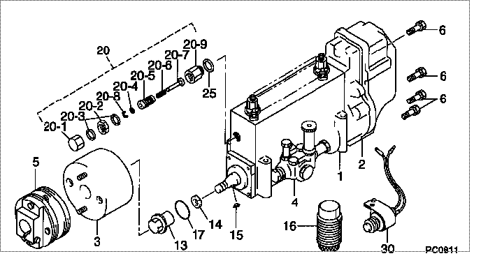
| 000. | [01] | 19000-02870 | PUMP ASSY, INJECTI | 22010-2210 |
| 001. | [01] | 09010-03141 | BODY ASSY, INJECTI | |
| 002. | [01] | 09080-04271 | GOVERNOR ASSY, MEC | |
| 003. | [01] | 09180-00962 | TIMER ASSY, AUTOMA | |
| 004. | [01] | 09210-01900 | PUMP ASSY, FUEL FE | 22570-1330A |
| 005. | [01] | 09250-00631 | COUPLING ASSY | 22610-1471A |
| 006. | [08] | 91518-06161 | BOLT, W/WASHER | 22815-1310A |
| 013. | [01] | 09001-20230 | NUT, TIMER ROUND | 22825-1110A |
| 014. | [01] | 94901-40070 | WASHER, COUNTERSUN | 22877-1190A |
| 015. | [01] | 90458-05750 | KEY, WOODRUFF | 22891-1070A |
| 016. | [01] | 09006-10011 | COVER, PRIMING PUM | 6 053 1552 60 |
| 017. | [01] | 90801-40280 | O-RING | 22817-1050A |
| 020. | [01] | 09002-00150 | CONTROL ASSY, TORO | |
| 020-001. | [01] | 09003-20090 | CAP | |
| 020-002. | [01] | 94905-30230 | NUT, HEXAGON, W/ H | |
| 020-003. | [02] | 94901-81210 | WASHER, COPPER PLA | |
| 020-004. | [1C] | 94901-31680 | WASHER, PLATE, SK | 6 056 1318 00 |
| 020-004. | [1C] | 94901-35080 | WASHER, PLATE, SK | 22885-1270A |
| 020-004. | [1C] | 94901-35090 | WASHER, PLATE, SK | 22885-1280A |
| 020-004. | [1C] | 94901-35100 | WASHER, PLATE, SK | 22885-1290A |
| 020-005. | [01] | 09002-60070 | SCREW, ADJUSTING | |
| 020-006. | [1C] | 09005-20110 | SPRING | |
| 020-006. | [1C] | 09005-20100 | SPRING | |
| 020-006. | [1C] | 09005-20070 | SPRING | |
| 020-007. | [01] | 09091-90230 | ADAPTER | |
| 020-008. | [01] | 09089-40010 | E-RING | 22863-1810A |
| 020-009. | [01] | 09001-80270 | COVER, CONTROL RAC | |
| 025. | [01] | 94901-80710 | WASHER, COPPER PLA | 22863-1300A |
| 030. | [01] | 09009-90180 | SWITCH KIT, CONTRO | 22690-1040 |
Include in #3:
19000-02870
as PUMP ASSY, INJECTI
Cross reference number
| Part num | Firm num | Firm | Name |
| 19000-02870 | 22010-2210 | PUMP ASSY, INJECTI | |
| 22010-2210 | HINO | PUMP ASSY, INJECTI |
Information:
Remove Flywheel Housing
Start By:a. remove crankshaft rear seal and wear sleeveb. remove oil pan 1. Fasten a hoist to implement pump (1) and remove the pump (if equipped). The weight of implement pump (1) is 29 kg (75 lb). 2. Remove plates (2).3. Remove pump drives (3) (if equipped) with Tool (A) and a hoist. The weight of each pump drive is 29 kg (65 lb). 4. Remove plate (4). 5. Remove starting motor (5) and disconnect oil supply line (6) at the flywheel housing. 6. Remove engine rear supports (7). 7. Remove turbocharger oil supply line (8) and bracket (9). 8. Remove top section of turbocharger heat shield (10). 9. Remove turbocharger drain line (11) and elbow (12). 10. Remove plate (13). 11. Remove bolts (14) and the remainder of the bolts which hold bracket (15) to the engine and remove bracket (15). 12. Use Tooling (A) and fasten a hoist to flywheel housing (16). Remove the bolts that hold flywheel housing (16) in position and pull flywheel housing off the dowels and remove it. The weight of the flywheel housing is 191 kg (425 lb).13. Put the flywheel housing in the position shown. 14. Remove bolts (17) from shafts (19).
Bearings (20) can fall out of gears (18) when the gears are removed from the flywheel housing.
15. Remove gears (18) from the flywheel housing. 16. Remove shafts (19), bearing cones (22), spacers (21) and bearing cones (20) from gears (18). 17. If necessary, remove bearing cups (23) and (25), spacers (24) and the snap rings from gears (18). The bearing cups will have damage after removal. Use new parts for replacement.Install Flywheel Housing
1. Install the snap rings in the groove in idler gear (2).2. Install the spacers for bearing cups (1) in gears (2) from the side of gears (2) that have the part number. Make sure the notches in the spacers are toward the snap rings. The snap rings are not in the center of the gear bores. The spacers must be installed in the gear bores that have the longer measurement from the snap ring to the surface of the gear.3. Lower the temperature of bearing cups (1) and install them in gears (2) until they make contact with the spacers. 4. Put the flywheel housing in the position shown and install bearing cones (3). 5. Put idler gears (2) in position on the bearing cones. Make sure the side of gears (2) with the part number is toward the flywheel housing. 6. Put spacer (4) on the inner race of the bearing cone. 7. Install bearing cones (5) in the gears. 8. Install shafts (6) and the bolts to hold them.
Put the No. 1 piston at top center to make an alignment of the timing marks on the crankshaft rear gear (9) with the balancer gear (8). Failure to follow this procedure can cause damage to the engine.
9. Clean the front face of the flywheel housing and the rear face of the cylinder