Information pump assy, injecti
Rating:
Components :
| 001. | PUMP ASSY, INJECTI | 19000-02322 |
| 002. | BODY ASSY, INJECTI | 09010-03373 |
| 003. | GOVERNOR ASSY, COM | 09070-00096 |
| 004. | TIMER ASSY, AUTOMA | 09180-01010 |
| 005. | PUMP ASSY, FUEL FE | 09210-01101 |
| 005. | PUMP ASSY, FUEL FE | 09210-01101 |
Scheme ###:
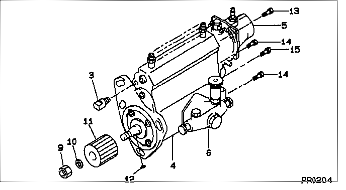
| 000. | [01] | 19000-02322 | PUMP ASSY, INJECTI | 22100-87337-000 |
| 003. | [01] | 09001-80061 | COVER, CONTROL RAC | 22166-46010-000 |
| 004. | [01] | 09010-03373 | BODY ASSY, INJECTI | 22120-56041-000 |
| 005. | [01] | 09070-00096 | GOVERNOR ASSY, COM | 22320-56041-000 |
| 006. | [01] | 09210-01101 | PUMP ASSY, FUEL FE | 22510-56040-000 |
| 009. | [01] | 09001-20020 | NUT, TIMER ROUND | 22611-46010-000 |
| 010. | [01] | 94901-50490 | WASHER, SPRING | 22173-46010-000 |
| 011. | [01] | 09257-50020 | SHAFT, SPLINE | 22174-47010-000 |
| 012. | [01] | 94913-00050 | KEY, WOODRUFF | 90099-13002-000 |
| 013. | [01] | 91518-08221 | BOLT, W/WASHER | 90091-20804-000 |
| 014. | [03] | 94904-70620 | BOLT, W/WASHER | 90099-04526-000 |
| 015. | [01] | 91418-06121 | BOLT, W/WASHER | 90091-20607-000 |
| 100. | [01] | 09180-01010 | TIMER ASSY, AUTOMA | 22610-56020-000 |
Include in #3:
19000-02322
as PUMP ASSY, INJECTI
Cross reference number
| Part num | Firm num | Firm | Name |
| 19000-02322 | 22100-8733 | PUMP ASSY, INJECTI |
Information:
1. Remove line (1) from the fuel ratio control. Remove two bolts (3), and remove solenoid (2) from the governor housing.2. Disconnect throttle linkage (4) from the lever assembly on the side of the governor housing. (A test application is shown in the photo.)3. Remove two bolts (5) from the front of the governor housing. Remove eight bolts (6), and remove governor housing (7). 4. Remove two bolts that hold fuel ratio control (8) to the governor housing. Unscrew the fuel ratio control from shaft (9) and remove it.5. Remove plug and seal (10) from the governor housing. 6. Remove two bolts (12) that hold lock (11) and flange (14) on fuel ratio control (8). Remove lock (11), flange (14), and O-ring seal (13) from the fuel ratio control.7. Check the condition of O-ring seal (13). If it is worn or damaged, make a replacement with a new part. 8. Remove ring (19) from the end of shaft (15). Remove lever assembly (18), spring (17), lever (16), spacer (21) and shaft (15) from the governor housing.9. Remove pin (20) from lever assembly (18) with a hammer and punch. Remove shaft (9) from the lever assembly. The following steps are for the installation of the fuel ratio control.10. Position shaft (9) in lever assembly (18) and install it with pin (20) using a hammer and punch.11. Install shaft (15), spacer (21), lever (16), spring (17) and lever assembly (18) in the governor housing. Install ring (19) on the end of shaft (15).12. Install O-ring seal (13) on fuel ratio control (8). Install flange (14) and lock (11) on the fuel ratio control with bolts (12).13. Install seal and plug (10) in the governor housing.14. Check the condition of the four O-ring seals on top of the governor housing where the fuel ratio control mounts. If any of the seals are worn or damaged, make a replacement with new parts.15. Screw fuel ratio control (8) onto shaft (9) approximately six turns. Install the fuel ratio control with the two bolts that hold it to the governor housing.16. Position governor housing (7), and install two bolts (5) on the front of the governor housing. Install eight bolts (6).17. Connect throttle linkage (4) to the lever assembly on the side of the governor housing.18. Install solenoid (2) with bolts (3). Install line (1) on the fuel ratio control.19. Make an adjustment to the fuel ratio control. See the topic, FUEL RATIO CONTROL ADJUSTMENT in the TESTING AND ADJUSTING section of this Module.