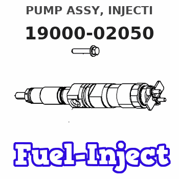
Information pump assy, injecti
Nozzle:
0935001720
Rating:
KIT List:
| Pump assy, fuel fe | 1922900060 |
Components :
| 001. | PUMP ASSY, INJECTI | 19000-02050 |
| 002. | SWITCH KIT, CONTRO | 09009-90230 |
| 003. | BODY ASSY, INJECTI | 09010-03173 |
| 004. | TIMER ASSY, AUTOMA | 09180-01090 |
| 005. | PUMP ASSY, FUEL FE | 09210-00920 |
| 006. | COUPLING ASSY | 09250-00270 |
Scheme ###:
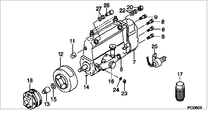
| 000. | [01] | 19000-02050 | PUMP ASSY, INJECTI | 22010-1671 |
| 006. | [01] | 09010-03173 | BODY ASSY, INJECTI | 22110-1131 |
| 007. | [01] | 09080-04911 | GOVERNOR ASSY, MEC | 22310-1250 |
| 008. | [06] | 94904-71150 | BOLT, W/WASHER | 6 306 1001 00 |
| 009. | [01] | 94904-73910 | BOLT, W/WASHER | 22815-2820A |
| 011. | [01] | 09001-80290 | COVER, CONTROL RAC | 22114-1020A |
| 012. | [01] | 09180-01090 | TIMER ASSY, AUTOMA | 22510-1140A |
| 013. | [01] | 09001-20180 | NUT, TIMER ROUND | 22511-1070A |
| 014. | [01] | 94913-00210 | KEY, WOODRUFF | 22895-1010A |
| 015. | [01] | 94901-50590 | WASHER, SPRING | 22877-1620A |
| 016. | [01] | 09210-00920 | PUMP ASSY, FUEL FE | 22570-1250A |
| 017. | [01] | 09006-10011 | COVER, PRIMING PUM | 6 053 1552 60 |
| 018. | [01] | 09250-00270 | COUPLING ASSY | 22610-1080A |
| 020. | [01] | 09031-00130 | VALVE ASSY, OVERFL | 22107-1090A |
| 022. | [02] | 94901-02480 | WASHER | 22847-1940A |
| 023. | [03] | 90160-06051 | NUT, HEXAGON | 22825-1480A |
| 024. | [03] | 90258-06001 | WASHER, SPRING | 28219-1110A |
| 025. | [01] | 09009-90230 | SWITCH KIT, CONTRO | 22690-1120 |
| 026. | [01] | 94918-00500 | SCREW, HOLLOW | 22835-1190A |
| 027. | [02] | 94901-02490 | WASHER | 22877-1100A |
Include in #3:
19000-02050
as PUMP ASSY, INJECTI
Cross reference number
| Part num | Firm num | Firm | Name |
| 19000-02050 | 22010-1671 | PUMP ASSY, INJECTI | |
| 22010-1671 | HINO | PUMP ASSY, INJECTI |
Information:
Remove & Install Water Temperature Regulators
There are two water temperature regulators, one for each cylinder head.1. Drain the coolant from the engine to a level below the water temperature regulators.
Typical Example2. Remove elbow (1). Remove tube and elbow (2). 3. Remove cover assemblies (3). 4. Remove water temperature regulator (4) from each cover assembly. 5. Remove lip-type seal (5) from each cover assembly if a replacement is necessary.6. Check the water temperature regulators. See Specifications Manual SENR6475. The following steps are for the installation of the water temperature regulators. 7. Use Tool (A) to install lip-type seals (5). Install the seals with the lip toward the inside of the covers. Install the seal until it contacts the counterbore in the cover assembly.
If the water temperature regulators are installed incorrectly the engine will over heat.
8. Put clean glycerin on the lip of seal (5), and install water temperature regulator (4) in each cover assembly (3). 9. Install new gaskets (6) and cover assemblies (3).
Typical Example10. Install the gaskets and elbow (1). Put clean engine oil or glycerin on the O-ring seals on tube (2). Install the gasket, tube and elbow (2).11. Fill the cooling system to the correct level. See the Operation & Maintenance Manual.