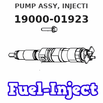
Information pump assy, injecti
Rating:
Components :
| 001. | PUMP ASSY, INJECTI | 19000-01923 |
| 002. | SWITCH KIT, CONTRO | 09009-90230 |
| 003. | BODY ASSY, INJECTI | 09010-03173 |
| 004. | TIMER ASSY, AUTOMA | 09180-00921 |
| 005. | PUMP ASSY, FUEL FE | 09210-00920 |
| 006. | COUPLING ASSY | 09250-00270 |
Scheme ###:
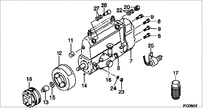
| 000. | [01] | 19000-01923 | PUMP ASSY, INJECTI | 22010-1594 |
| 006. | [01] | 09010-03173 | BODY ASSY, INJECTI | 22110-1131 |
| 007. | [01] | 09080-04911 | GOVERNOR ASSY, MEC | 22310-1250 |
| 008. | [06] | 94904-71150 | BOLT, W/WASHER | 6 306 1001 00 |
| 009. | [01] | 94904-73910 | BOLT, W/WASHER | 22815-2820A |
| 011. | [01] | 09001-80290 | COVER, CONTROL RAC | 22114-1020A |
| 012. | [01] | 09180-00921 | TIMER ASSY, AUTOMA | 22510-1080A |
| 013. | [01] | 09001-20180 | NUT, TIMER ROUND | 22511-1070A |
| 014. | [01] | 94913-00210 | KEY, WOODRUFF | 22895-1010A |
| 015. | [01] | 94901-50590 | WASHER, SPRING | 22877-1620A |
| 016. | [01] | 09210-00920 | PUMP ASSY, FUEL FE | 22570-1250A |
| 017. | [01] | 09006-10011 | COVER, PRIMING PUM | 6 053 1552 60 |
| 018. | [01] | 09250-00270 | COUPLING ASSY | 22610-1080A |
| 020. | [01] | 09031-00130 | VALVE ASSY, OVERFL | 22107-1090A |
| 022. | [02] | 94901-02480 | WASHER | 22847-1940A |
| 023. | [03] | 90160-06051 | NUT, HEXAGON | 22825-1480A |
| 024. | [03] | 90258-06001 | WASHER, SPRING | 28219-1110A |
| 025. | [01] | 09009-90230 | SWITCH KIT, CONTRO | 22690-1120 |
| 026. | [01] | 94918-00500 | SCREW, HOLLOW | 22835-1190A |
| 027. | [02] | 94901-02490 | WASHER | 22877-1100A |
Include in #3:
19000-01923
as PUMP ASSY, INJECTI
Cross reference number
| Part num | Firm num | Firm | Name |
| 19000-01923 | 22010-1594 | PUMP ASSY, INJECTI |
Information:
Disassemble Fuel Injection Pump Housing
Start By:a. remove fuel injection pump housing and governorb. remove governor
Be careful not to cause damage to the inlet and outlet ports on the bottom of the pump housing. The pump housing must be put on wood blocks before it is disassembled.
1. Remove housing (1) and the gasket. 2. Remove the shaft and gear (2) from housing (1). 3. Remove bearing (3) from housing (1). Bearing (3) will be destroyed when it is removed. 4. Remove two bolts (4), and remove cover (5). 5. Remove bolts (9) that hold retainer (7) and gear (6) to the fuel injection pump camshaft. Remove the retainer and gear. When pinion gear (8) is removed, make a replacement of drive gear (11) with a new part.6. Remove idler gear (10). Remove drive gear (11) and pinion shaft (8). Use a soft hammer to push pinion shaft (8) out of drive gear (11). 7. Remove protective caps (14), felt washers (13) and plug (12). 8. Install Tool (A) in the hole with the large diameter end without the taper down. Move the governor control to the "ON" position until the rack stops against Tool (A). The racks are now in center (zero) position. Hold the rack against Tool (A), and carefully remove each fuel injection pump (15) with Tools (B) and (C).
When injection pumps, spacers and lifters are removed from the injection pump housing, keep the parts of each pump together so they can be installed in their original location.
9. Remove bracket assembly (16) and link (17). 10. Put identification marks on fuel racks (18) and (19), and remove the fuel racks. 11. Put identification marks on each spacer (20) and lifter (21) so they can be installed in their original position. 12. Remove fuel injection pump camshaft (22) from the pump housing.13. Remove O-ring seal (23). 14. Inspect link pivot shaft (24) and bracket locating pin (25). Make a replacement by removal of shaft (24) and dowel (25) with Tool (D). 15. Inspect upper bearing (26) and the lower bearing that hold the pinion gear in the pump housing.16. Make a replacement of bearings (26) if necessary.17. Inspect idler gear shaft (27). If a replacement is necessary, remove the shaft with Tooling (D). 18. Inspect fuel rack bearings (28) and camshaft bearings (29). If a replacement is necessary, remove bearings (28) and (29).19. Use Tooling (E) to remove bearings (28). 20. Remove regulator valve (30). 21. Remove pin (31) to disassemble the regulator valve, and inspect the components.22. Piston (32) must move freely in valve body (30).23. Make a reference to the Specifications for spring (34).24. Make a replacement of O-ring seals (33).Assemble Fuel Injection Pump Housing
Pin (2) must not extend out of either side of valve body (3).
1. Install spring (4), piston (1) and pin (2) in valve body (3).2. Put clean engine oil on the valve body and O-ring seals (5). Install the oil bypass valve in the pump housing. Tighten the bypass valve body to