Information pump assy, injecti
Rating:
Components :
| 001. | PUMP ASSY, INJECTI | 19000-01811 |
| 002. | BODY ASSY, INJECTI | 09010-01712 |
| 003. | COVER, BEARING | 09020-10110 |
| 004. | TIMER ASSY, AUTOMA | 09180-01021 |
| 005. | PUMP ASSY, FUEL FE | 09210-01900 |
| 006. | COUPLING ASSY | 09250-00152 |
Scheme ###:
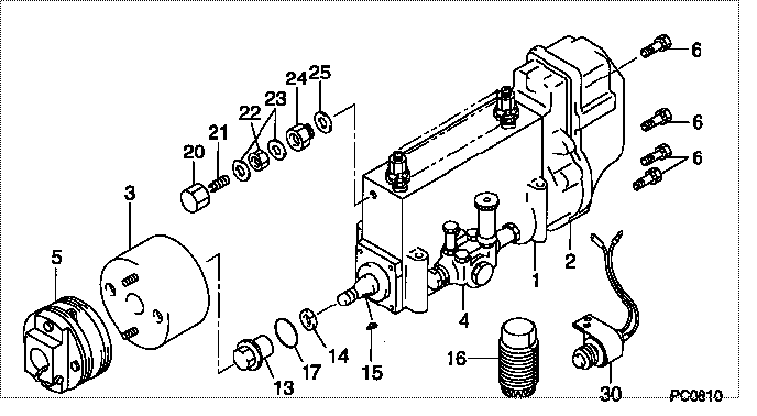
| 000. | [01] | 19000-01811 | PUMP ASSY, INJECTI | 22010-1700 |
| 001. | [01] | 09010-01712 | BODY ASSY, INJECTI | 6 075 1202 40 |
| 002. | [01] | 09130-00262 | GOVERNOR ASSY, MEC | 22310-1600 |
| 003. | [01] | 09180-01021 | TIMER ASSY, AUTOMA | 22510-1120A |
| 004. | [01] | 09210-01900 | PUMP ASSY, FUEL FE | 22570-1330A |
| 005. | [01] | 09250-00152 | COUPLING ASSY | 22610-1140A |
| 006. | [08] | 91518-06161 | BOLT, W/WASHER | 22815-1310A |
| 013. | [01] | 09001-20230 | NUT, TIMER ROUND | 22825-1110A |
| 014. | [01] | 94901-40070 | WASHER, COUNTERSUN | 22877-1190A |
| 015. | [01] | 90458-05750 | KEY, WOODRUFF | 22891-1070A |
| 016. | [01] | 09006-10011 | COVER, PRIMING PUM | 6 053 1552 60 |
| 017. | [01] | 90801-40280 | O-RING | 22817-1050A |
| 020. | [01] | 09003-20040 | CAP | 22342-1110A |
| 021. | [01] | 09002-60050 | SCREW, ADJUSTING | 22396-1140A |
| 022. | [01] | 94805-30100 | NUT, HEXAGON, W/HO | 22885-3830A |
| 023. | [02] | 94901-80350 | WASHER, COPPER PLA | 22847-1950A |
| 024. | [01] | 09001-80152 | COVER, CONTROL RAC | 22372-1100A |
| 025. | [01] | 94901-80710 | WASHER, COPPER PLA | 22863-1300A |
| 030. | [01] | 09009-90190 | SWITCH KIT, CONTRO | 22690-1080A |
Include in #3:
19000-01811
as PUMP ASSY, INJECTI
Cross reference number
| Part num | Firm num | Firm | Name |
| 19000-01811 | 22010-1700 | PUMP ASSY, INJECTI |
Information:
Disassemble Fuel Transfer Pump
Start By:a. remove fuel transfer pump 1. Remove tachometer drive (3) from transfer pump cover (4).2. Remove bolts (1). Separate cover (4) and pump body (2). 3. Remove lip-type seal (6) from the cover. Remove plug (5), the seal, spring and plunger (bypass valve) from the cover. 4. Remove nut (10) from shaft (7). Remove gear (9) and key (11).5. Remove shaft (7) and gear (8) as a unit. Remove gear (8) from drive shaft (7) with a press.6. Remove idler gear (12). 7. Remove bushing (14), two lip-type seals and the bottom bearing from pump body (2).8. Remove check valve (13).Assemble Fuel Transfer Pump
1. Install bushing (4) in body (3) with Tooling (B). The bushing must be .80 .50 mm (.031 .020 in) below the (gear) surface of the body.2. Install the check valve in the body with Tooling (A).3. Install lip-type seal (5) with Tooling (C). Install the seal until it is 26.19 .13 mm (1.031 .005 in) from the bottom (drive gear) surface of body (3) and with the lip toward bushing (4) as shown.4. Install lip-type seal (6) with Tooling (D). Install the seal until it is 14.2 0.5 mm (.559 .020 in) from the bottom (drive gear) surface of body (3) and with the lip away from seal (5) as shown.5. Install bearing (7) in body (3) with Tooling (E). The bearing must be even with the bottom (drive gear) surface of the pump body. 6. Heat gear (8) to a maximum temperature of 315° C (600° F). Install gear (8) on shaft (11) until dimension (X) is 49.71 0.25 mm (1.957 .010 in).7. Install the drive shaft and gear in body (3). Install the key, gear (10) and nut (9). Tighten the nut to a torque of 30 7 N m (22 5 lb ft).8. Install idler gear (12) in body (3).9. Install lip-type seal (2) with Tooling (C). Install the seal until it is 22.61 .05 mm (.890 .002 in) from the top surface of cover (1) with the lip toward the inside as shown. 10. Install plunger (14) (bypass valve), spring (15) and seal and plug (13) in pump cover (1). Tighten plug (13) to a torque of 37 4 N m (27 3 lb ft).
Do not let the liquid gasket enter the pump during application or assembly.
11. Put 7M-7260 Liquid Gasket Material on the surface of cover (1). Install cover (1) on pump body (3). The drive shaft must turn freely after the bolts that hold the transfer pump together are tightened.12. Install the tachometer drive on cover (1).End By:a. install fuel transfer pump