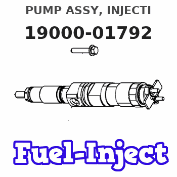
Information pump assy, injecti
Rating:
Components :
| 001. | PUMP ASSY, INJECTI | 19000-01792 |
| 002. | BODY ASSY, INJECTI | 09010-03021 |
| 003. | BODY ASSY, INJECTI | 09010-04861 |
| 004. | PUMP ASSY, FUEL FE | 09210-01020 |
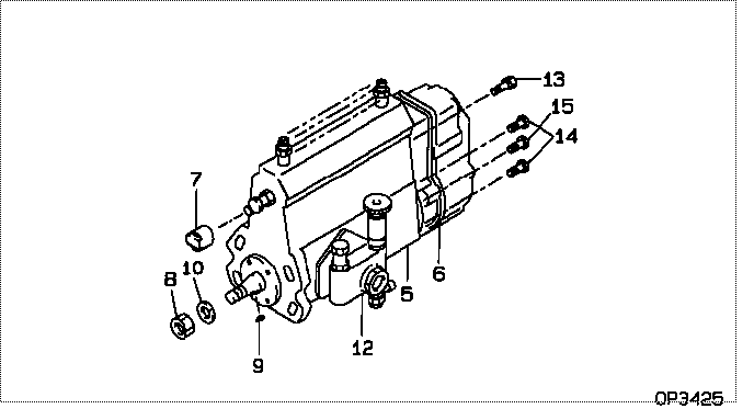
Scheme ###:
| 000. | [01] | 19000-01792 | PUMP ASSY, INJECTI | ME008315 |
| 005. | [01] | 09010-03021 | BODY ASSY, INJECTI | 31761-82100 |
| 005. | [01] | 09010-04861 | BODY ASSY, INJECTI | ME703936 |
| 006. | [01] | 09080-04961 | GOVERNOR ASSY, MEC | |
| 007. | [01] | 09001-80081 | COVER, CONTROL RAC | ME702034 |
| 008. | [01] | 94905-02450 | NUT, HEXAGON | ME008351 |
| 009. | [01] | 94913-00190 | KEY, WOODRUFF | ME703361 |
| 010. | [01] | 94901-50500 | WASHER, SPRING | ME008373 |
| 012. | [01] | 09210-01020 | PUMP ASSY, FUEL FE | ME019618 |
| 013. | [01] | 91518-08221 | BOLT, W/WASHER | MM500963 |
| 014. | [05] | 94900-50191 | SCREW, SLOTTED FLA | ME022439 |
| 015. | [01] | 94900-50242 | SCREW, SLOTTED FLA |
Include in #3:
19000-01792
as PUMP ASSY, INJECTI
Cross reference number
| Part num | Firm num | Firm | Name |
| 19000-01792 | ME008315 | PUMP ASSY, INJECTI |
Information:
Remove & Install Fuel Ratio Control
1. Disconnect boost hose (2) at fuel ratio control (1).2. Remove lockwire (3) and the seal from the bolts.3. Remove the two bolts that hold fuel ratio control (1).4. Pull up on the fuel ratio control, and move it toward the front of the engine so the valve on the fuel ratio will disengage with the groove (slot) in the governor collar. Remove the fuel ratio control and gasket. The following steps are for installation of the fuel ratio control.5. Install a new gasket on fuel ratio control (1).6. Engage valve (4) with the groove (slot) in collar (5) for the governor.7. Install the bolts that hold fuel ratio control (1) to the governor plate.8. Connect boost hose (2) to the fuel ratio control.9. Install new lockwire (3) and seal. See Fuel Rack Setting in Testing And Adjusting.10. Lower the hoods.Disassemble Fuel Ratio Control
Start By:a. remove fuel ratio control The illustrations which follow show a different design fuel ratio control. However, the service procedure is the same. 1. Remove two bolts (1) and cover (2). 2. Remove valve assembly (3).3. Remove seal (4) and the O-ring seal from the valve assembly.4. Remove retainer (5) and two springs (6). 5. Remove the three bolts from the cover. Remove cover (12) and gasket (11).6. Remove valve (13), diaphragm (8), retainer (9) and spring (10).7. Remove pin (14) from valve (13).8. Remove cover (7) from the valve.Assemble Fuel Ratio Control
The illustrations which follow show a different design fuel ratio control. However, the service procedure is the same. 1. Put clean SAE 30 Oil on the seal. Install seal (1) in cover (2) with the lip of the seal toward the inside of the cover. 2. Install valve (3) in cover (2).3. Install the pin that holds the cover on the valve. 4. Install the spring and the retainer in cover (6).5. Install diaphragm (5) on valve assembly (4) and in the cover.6. Install cover (8). Install three bolts (7) that hold the cover in position. 7. Put clean SAE 30 Oil on the seal and the ring seal. Install seals (11) on the valve.8. Install two springs (12), retainer (13) and valve assembly (10).9. Install housing (9) and the bolts.
Correct adjustment must be made to fuel ratio control before installation. See the topic "Adjustment Of Air Fuel Ratio Control" in Testing & Adjusting.
End By:a. install fuel ratio control