Information pump assy, injecti
Rating:
Components :
| 001. | PUMP ASSY, INJECTI | 19000-01783 |
| 002. | BODY ASSY, INJECTI | 09010-03831 |
| 003. | TIMER ASSY, AUTOMA | 09180-01040 |
| 003. | TIMER ASSY, AUTOMA | 09180-01040 |
| 004. | PUMP ASSY, FUEL FE | 09210-01091 |
Scheme ###:
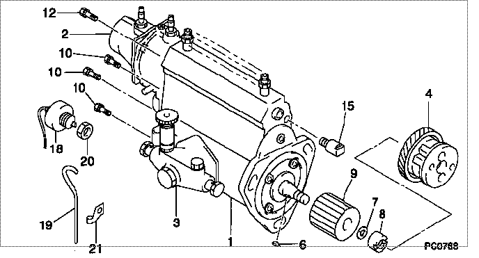
| 000. | [01] | 19000-01783 | PUMP ASSY, INJECTI | 22100-48101 |
| 001. | [01] | 09010-03831 | BODY ASSY, INJECTI | 22120-48110 |
| 002. | [01] | 09070-00222 | GOVERNOR ASSY, COM | 22320-48040 |
| 003. | [01] | 09210-01091 | PUMP ASSY, FUEL FE | 22510-48032 |
| 004. | [01] | 09180-01040 | TIMER ASSY, AUTOMA | 22610-48020 |
| 006. | [01] | 94913-00050 | KEY, WOODRUFF | 90099-13002 |
| 007. | [01] | 94901-50490 | WASHER, SPRING | 22173-46010 |
| 008. | [01] | 09001-20020 | NUT, TIMER ROUND | 22611-46010 |
| 009. | [01] | 09257-50020 | SHAFT, SPLINE | 22174-47010 |
| 010. | [04] | 94904-70620 | BOLT, W/WASHER | 90099-04526 |
| 012. | [01] | 91518-08221 | BOLT, W/WASHER | 90091-20804 |
| 015. | [01] | 09001-80061 | COVER, CONTROL RAC | 22116-46010 |
| 018. | [01] | 09071-00040 | BELLOWS ASSY, PNEU | 22680-48062 |
| 019. | [01] | 94933-03581 | TUBE, RUBBER | 90099-33044 |
| 020. | [01] | 94905-30241 | NUT, HEXAGON, W/ H | 90099-05137 |
| 021. | [01] | 94935-03042 | CLIP, CORD | 90099-35023 |
Include in #3:
19000-01783
as PUMP ASSY, INJECTI
Cross reference number
| Part num | Firm num | Firm | Name |
| 19000-01783 | 22100-4810 | PUMP ASSY, INJECTI |
Information:
2. Remove guide (5), spring (4) and plunger (3) from the cover. 3. Remove O-ring seal (6) from the back of the cover. 4. Remove inner rotor (7) and outer rotor (8) from the timing gear cover. 5. Measure the inside diameter of bearing (9). The inside diameter must be 71.22 0.05 mm (2.804 .002 in.). Remove bearing (9) only if a replacement is necessary. Remove shaft (10) if a replacement is necessary. Install Oil Pump And Relief Valve
1. Thoroughly clean all of the parts. Put oil on all of the pump parts. 2. If the bearing was removed from the timing gear cover, install a new bearing with tool (A). Make sure the bearing is installed with the joint in the position shown in the illustration. 3. If the shaft was removed from the timing gear cover, install the new shaft so dimension "X" from the top of the shaft to the counterbore in the cover is 36.14 0.25 mm (1.423 .010 in.). 4. Install inner rotor (1) and outer rotor (2) in the timing gear cover.5. Measure the clearance between the rotors with a feeler gauge. The clearance must be 0.05 to 0.20 mm (.002 to .008 in.). The maximum permissible clearance is 0.28 mm (.011 in.). Make a replacement of BOTH rotors if the clearance is not correct. The rotors can not be ordered separately.6. Put plunger (3), spring (4) and guide (5) in the cover. Use a 1-1/8 in. crowfoot wrench and torque wrench to tighten guide (5) to a torque of 41 7 N m (30 5 lb.ft.). A slide rule type torque computer, Form No. SEHS7150, is available to find the torque wrench dial reading for different extensions. 7. Install O-ring seal (6) on the cover and put the cover in position on the timing gear cover. Install the locks and bolts that hold the cover in place. 8. Check the oil pump and clearance with a feeler gauge. The end clearance must be 0.069 to 0.135 mm (.0027 to .0053 in.). If the clearance is not correct, make a replacement of BOTH rotors or the cover.end by:a) install timing gear cover and oil pump.
1. Thoroughly clean all of the parts. Put oil on all of the pump parts. 2. If the bearing was removed from the timing gear cover, install a new bearing with tool (A). Make sure the bearing is installed with the joint in the position shown in the illustration. 3. If the shaft was removed from the timing gear cover, install the new shaft so dimension "X" from the top of the shaft to the counterbore in the cover is 36.14 0.25 mm (1.423 .010 in.). 4. Install inner rotor (1) and outer rotor (2) in the timing gear cover.5. Measure the clearance between the rotors with a feeler gauge. The clearance must be 0.05 to 0.20 mm (.002 to .008 in.). The maximum permissible clearance is 0.28 mm (.011 in.). Make a replacement of BOTH rotors if the clearance is not correct. The rotors can not be ordered separately.6. Put plunger (3), spring (4) and guide (5) in the cover. Use a 1-1/8 in. crowfoot wrench and torque wrench to tighten guide (5) to a torque of 41 7 N m (30 5 lb.ft.). A slide rule type torque computer, Form No. SEHS7150, is available to find the torque wrench dial reading for different extensions. 7. Install O-ring seal (6) on the cover and put the cover in position on the timing gear cover. Install the locks and bolts that hold the cover in place. 8. Check the oil pump and clearance with a feeler gauge. The end clearance must be 0.069 to 0.135 mm (.0027 to .0053 in.). If the clearance is not correct, make a replacement of BOTH rotors or the cover.end by:a) install timing gear cover and oil pump.