Information pump assy, injecti
Nozzle:
0935001180
Rating:
KIT List:
| Pump assy, fuel fe | 1922900060 |
Components :
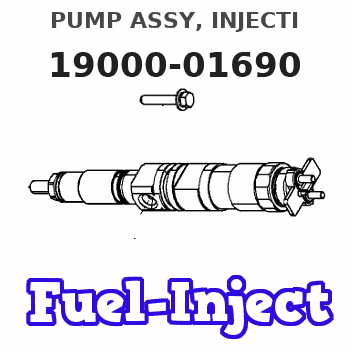
| 001. | PUMP ASSY, INJECTI | 19000-01690 |
| 002. | BODY ASSY, INJECTI | 09010-01960 |
| 003. | PUMP ASSY, FUEL FE | 09210-00372 |
Scheme ###:
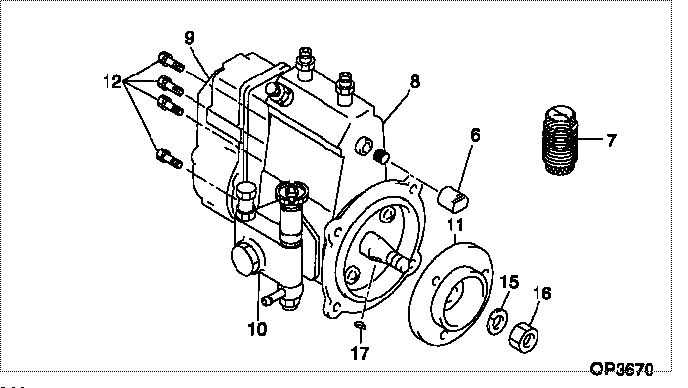
| 000. | [01] | 19000-01690 | PUMP ASSY, INJECTI | 131016380 |
| 006. | [01] | 09001-80140 | COVER, CONTROL RAC | |
| 007. | [01] | 09006-10011 | COVER, PRIMING PUM | |
| 008. | [01] | 09010-01960 | BODY ASSY, INJECTI | |
| 009. | [01] | 09080-02120 | GOVERNOR ASSY, MEC | |
| 010. | [01] | 09210-00372 | PUMP ASSY, FUEL FE | |
| 011. | [01] | 09255-10181 | BLOCK, COUPLING | |
| 012. | [06] | 94900-50191 | SCREW, SLOTTED FLA | |
| 015. | [01] | 90258-12001 | WASHER, SPRING | |
| 016. | [01] | 94905-02450 | NUT, HEXAGON | |
| 017. | [01] | 94913-00190 | KEY, WOODRUFF |
Include in #3:
19000-01690
as PUMP ASSY, INJECTI
Cross reference number
| Part num | Firm num | Firm | Name |
| 19000-01690 | 131016380 | PUMP ASSY, INJECTI | |
| 131016380 | ISHIKAWAJIMA | PUMP ASSY, INJECTI |
Information:
Remove Crankshaft
Start By:a. remove flywheel housingb. remove timing gear coverc. remove oil pan plated. remove oil pump The procedure for crankshaft removal is the same on both 3304 and 3306 Engines. The illustration in the procedure which follows is of a 3306 Engine.1. Install the engine on Tool (A) with the crankshaft in a horizontal position and on top. 2. Turn the crankshaft until the timing mark "C" on crankshaft gear (1) is in alignment with the timing mark "C" on camshaft gear (2) as shown in the inset. 3. Remove nuts (4), the connecting rod bolts and connecting rod caps (3) from the connecting rods.
If the piston and connecting rod assemblies are pushed down too far in the cylinder liners, the piston can hit the fuel injection nozzle or the intake exhaust valve which can cause damage to the fuel injection nozzle or the piston.
If the intake and exhaust valves are closed, it can be difficult to push the piston and connecting rod assembly down in the cylinder liner.4. Push the pistons that are not at top center down far enough to clear the crankshaft.5. Remove main bearing cap bolts (5) and main bearing caps (6) from the engine. 6. Remove thrust bearings (7) from the rear main bearing. 7. Install Tool (B) on crankshaft (8) as shown, and fasten a hoist to it. Lift the crankshaft straight up from the cylinder block. The weight of the crankshaft for 3304 Engines is 65 kg (143 lb). The weight of the crankshaft for 3306 Engines is 95 kg (210 lb). 8. Use Tool (C), and remove crankshaft gear (1) from the crankshaft.
If the bearings are to be removed, put identification marks on them as to their location for installation purposes.
9. If necessary, remove the main bearings from the cylinder block and main bearing caps. If necessary, remove the connecting rod bearings from the connecting rods and connecting rod caps.Install Crankshaft
1. Put the engine in position on Tool (A). Install the bearings dry when the clearance checks are made. Put clean engine oil on all the bearings for final assembly.
Make sure the upper and lower halves of the main bearings are installed so the bearing tabs fit into the notch in the cylinder block and main bearing caps.
2. If the bearings were removed from the engine, clean the bearing surfaces in the cylinder block and the connecting rods. Install the upper halves of connecting rod bearings (1) and main bearings (2). 3. Heat crankshaft gear (3) to a maximum temperature of 316° C (600° F). Install the gear on the crankshaft. 4. Install Tool (B) on the ends of the crankshaft and fasten a hoist to it.5. Make an alignment of the connecting rods with the crankshaft. Make an alignment of the "C" marks on crankshaft gear (3) and camshaft gear (4). When the connecting rods and the "C" marks are in alignment, lower the crankshaft on to the main bearings, and remove Tool (B). When the bearing clearance