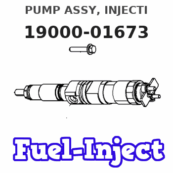
Information pump assy, injecti
Rating:
Components :
| 001. | PUMP ASSY, INJECTI | 19000-01673 |
| 002. | BODY ASSY, INJECTI | 09010-03472 |
| 003. | GOVERNOR ASSY, MEC | 09080-04492 |
| 004. | TIMER ASSY, AUTOMA | 09180-00921 |
| 005. | PUMP ASSY, FUEL FE | 09210-00920 |
| 006. | COUPLING ASSY | 09250-00270 |
Scheme ###:
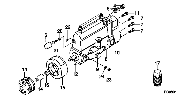
| 000. | [01] | 19000-01673 | PUMP ASSY, INJECTI | 22010-1772 |
| 004. | [01] | 09031-00130 | VALVE ASSY, OVERFL | 22107-1090A |
| 005. | [02] | 94901-02480 | WASHER | 22847-1940A |
| 006. | [01] | 09001-80401 | COVER, CONTROL RAC | 22114-1160A |
| 007. | [06] | 94904-71150 | BOLT, W/WASHER | 6 306 1001 00 |
| 008. | [01] | 09010-03472 | BODY ASSY, INJECTI | 22110-1191 |
| 009. | [01] | 09210-00920 | PUMP ASSY, FUEL FE | 22570-1250A |
| 010. | [01] | 09080-04492 | GOVERNOR ASSY, MEC | 22310-1140 |
| 011. | [01] | 94904-73910 | BOLT, W/WASHER | 22815-2820A |
| 012. | [01] | 94913-00210 | KEY, WOODRUFF | 22895-1010A |
| 013. | [01] | 09250-00270 | COUPLING ASSY | 22610-1080A |
| 014. | [01] | 09001-20180 | NUT, TIMER ROUND | 22511-1070A |
| 015. | [01] | 09180-00921 | TIMER ASSY, AUTOMA | 22510-1080A |
| 016. | [01] | 94901-50590 | WASHER, SPRING | 22877-1620A |
| 017. | [01] | 09006-10011 | COVER, PRIMING PUM | 6 053 1552 60 |
| 020. | [01] | 90170-06361 | NUT, HEXAGON | 92100-6040A |
| 021. | [01] | 09003-10070 | SCREW, CONTROL RAC | 22396-1210A |
| 022. | [01] | 09045-90030 | PIN | 22358-1010A |
| 023. | [03] | 90160-06051 | NUT, HEXAGON | 22825-1480A |
| 024. | [03] | 90258-06001 | WASHER, SPRING | 28219-1110A |
Include in #3:
19000-01673
as PUMP ASSY, INJECTI
Cross reference number
| Part num | Firm num | Firm | Name |
| 19000-01673 | 22010-1772 | PUMP ASSY, INJECTI |
Information:
Install Crankcase Ventilator Valve
1. Put gasket (2) and ventilator valve (1) in position. 2. Install the bolts and tighten them to a torque of 3.4 0.5 N m (30 4 lb.in.).Disassemble Crankcase Ventilator Valve
The crankcase ventilator valve can be disassembled while installed on the engine. The valve was removed for better photo illustration.1. Remove screws (2) that hold cover (3) on housing (1). 2. Remove cover (3) and spring (4) from the housing. 3. Remove the piston, sleeve (8), retainer (9), and diaphragm (7) from the housing as a unit. 4. Remove inner sleeve (6) and gasket (5) from the housing. 5. Remove nut (12), washer (13), spacer (11), piston (10), diaphragm (7), and the retainer from sleeve (8).Assemble Crankcase Ventilator Valve
1. Put 5H2471 Gasket Cement on both sides of gasket (2). Install the gasket on housing (1). 2. Install inner sleeve (3) in the housing.3. Put piston (6) in position next to the side of diaphragm (4) that has identification "PISTON SIDE".4. Put retainer (5) in the diaphragm. 5. Put the screw through sleeve (7), retainer, diaphragm, and the piston.6. Install spacer (8), washer, and nut (9) on the screw. 7. Put 5H2471 Gasket Cement on the contact surfaces of the diaphragm. Install the sleeve, retainer, diaphragm, and piston in the inner sleeve and housing.8. Put the spring and cover in position on the housing and install the screws that hold the cover in place.