Information pump assy, injecti
Rating:
Components :
| 001. | PUMP ASSY, INJECTI | 19000-01622 |
| 002. | BODY ASSY, INJECTI | 09010-03831 |
| 003. | TIMER ASSY, AUTOMA | 09180-01040 |
| 003. | TIMER ASSY, AUTOMA | 09180-01040 |
| 004. | PUMP ASSY, FUEL FE | 09210-00971 |
Scheme ###:
| 000. | [01] | 19000-01622 | PUMP ASSY, INJECTI | 22100-48081 |
| 001. | [01] | 09010-03831 | BODY ASSY, INJECTI | 22120-48110 |
| 002. | [01] | 09070-00282 | GOVERNOR ASSY, COM | 22320-48080 |
| 003. | [01] | 09210-00971 | PUMP ASSY, FUEL FE | 22510-77130 |
| 004. | [01] | 09180-01040 | TIMER ASSY, AUTOMA | 22610-48020 |
| 006. | [01] | 94913-00050 | KEY, WOODRUFF | 90099-13002 |
| 007. | [01] | 94901-50490 | WASHER, SPRING | 22173-46010 |
| 008. | [01] | 09001-20020 | NUT, TIMER ROUND | 22611-46010 |
| 009. | [01] | 09257-50020 | SHAFT, SPLINE | 22174-47010 |
| 010. | [04] | 94904-70620 | BOLT, W/WASHER | 90099-04526 |
| 012. | [01] | 91518-08221 | BOLT, W/WASHER | 90091-20804 |
| 015. | [01] | 09001-80061 | COVER, CONTROL RAC | 22116-46010 |
| 018. | [01] | 09071-00040 | BELLOWS ASSY, PNEU | 22680-48062 |
| 019. | [01] | 94933-03581 | TUBE, RUBBER | 90099-33044 |
| 020. | [01] | 94905-30241 | NUT, HEXAGON, W/ H | 90099-05137 |
| 021. | [01] | 94935-03042 | CLIP, CORD | 90099-35023 |
Include in #3:
19000-01622
as PUMP ASSY, INJECTI
Cross reference number
| Part num | Firm num | Firm | Name |
| 19000-01622 | 22100-4808 | PUMP ASSY, INJECTI |
Information:
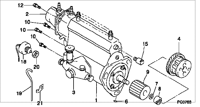
Illustrations show fuel injection pump housing and governor removed from engine. Service work can be done with it installed on engine.1. Remove air bleed lines (2). 2. Remove bolts (1), flange (3), the flange assembly and the gaskets.3. Remove the bolts and the cover. 4. Remove bolts (5), solenoid (4) and the gasket.5. Remove two bolts (7) and fuel ratio control (6).6. Remove the shutoff housing from the cover. 7. Remove the bolts, lever (10) and shaft (8).8. Remove the bolts, lever (9) and shaft (11).9. Remove seal (12) from the shutoff housing. Install Shutoff Housing
1. Put 5S1454 Sealing Compound on the outside diameter of the seal and install the seal (1) with tooling (A) in the shutoff housing with the lip toward the outside. The outer face of the seal must be 1.0 mm (.039 in.) below the surface of the housing. Remove the extra sealing compound from the housing and the seal after installation. 2. Put shaft (5) in position in housing (4).3. Install lever (6) and the bolts. 4. Install shaft (2), lever (3) and the bolts. Make an alignment of the notch in shaft (2) with lever (3). 5. Put cover (7) in position on shutoff housing assembly (8) and install the bolts.6. Put fuel ratio control (10) in position and install the bolts. 7. Install the gasket, solenoid (9) and bolts on the cover.8. Put the cover in position and install the bolts.9. Install the gasket, flange assembly, gasket, flange (11) and the bolts.10. Connect air bleed lines (12).
1. Put 5S1454 Sealing Compound on the outside diameter of the seal and install the seal (1) with tooling (A) in the shutoff housing with the lip toward the outside. The outer face of the seal must be 1.0 mm (.039 in.) below the surface of the housing. Remove the extra sealing compound from the housing and the seal after installation. 2. Put shaft (5) in position in housing (4).3. Install lever (6) and the bolts. 4. Install shaft (2), lever (3) and the bolts. Make an alignment of the notch in shaft (2) with lever (3). 5. Put cover (7) in position on shutoff housing assembly (8) and install the bolts.6. Put fuel ratio control (10) in position and install the bolts. 7. Install the gasket, solenoid (9) and bolts on the cover.8. Put the cover in position and install the bolts.9. Install the gasket, flange assembly, gasket, flange (11) and the bolts.10. Connect air bleed lines (12).