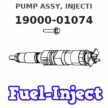
Information pump assy, injecti

Rating:
Components :
| 001. | PUMP ASSY, INJECTI | 19000-01074 |
| 002. | BODY ASSY, INJECTI | 09010-03244 |
| 003. | GOVERNOR ASSY, COM | 09070-00023 |
| 004. | TIMER ASSY, AUTOMA | 09180-01001 |
| 005. | PUMP ASSY, FUEL FE | 09210-00971 |
| 006. | COUPLING ASSY | 09240-00161 |
Scheme ###:
| 000. | [01] | 19000-01074 | PUMP ASSY, INJECTI | 22100-77241 |
| 001. | [01] | 09010-03244 | BODY ASSY, INJECTI | 22120-77131 |
| 002. | [01] | 09070-00024 | GOVERNOR ASSY, COM | 22320-77020 |
| 003. | [01] | 09210-00971 | PUMP ASSY, FUEL FE | 22510-77130 |
| 004. | [01] | 09180-01001 | TIMER ASSY, AUTOMA | 22610-77040 |
| 005. | [01] | 09243-60020 | COUPLING, INJECTIO | 22632-66010 |
| 006. | [01] | 09240-00161 | COUPLING ASSY | 22630-77051 |
| 009. | [01] | 09001-80010 | COVER, CONTROL RAC | 22116-77020 |
| 010. | [01] | 94913-00050 | KEY, WOODRUFF | 90099-13002 |
| 011. | [01] | 09001-20010 | NUT, TIMER ROUND | 22611-77020 |
| 012. | [01] | 90258-12001 | WASHER, SPRING | 94511-01200 |
| 013. | [01] | 09006-10011 | COVER, PRIMING PUM | 22511-77020 |
| 014. | [01] | 91518-08221 | BOLT, W/WASHER | 90091-20804 |
| 016. | [01] | 94905-30241 | NUT, HEXAGON, W/ H | 90099-05137 |
| 019. | [04] | 94904-70620 | BOLT, W/WASHER | 90099-04526 |
| 020. | [01] | 09071-00023 | BELLOWS ASSY, PNEU | 22680-77140 |
Include in #3:
19000-01074
as PUMP ASSY, INJECTI
Cross reference number
| Part num | Firm num | Firm | Name |
| 19000-01074 | 22100-7724 | PUMP ASSY, INJECTI |
Information:
Camshaft Gear Assembly
View A-A(8) Distance from the end of 9N5771 Dowell to the face of gear ... 11.81 0.13 mm(.465 .005 in)
View B-B(9) Distance from the end of 5P4283 Dowel to the face of camshaft ... 2.00 0.25 mm(.079 .010 in)Camshaft Installation
For installation of camshaft, the timing mark on the camshaft gear tooth must be in alignment with the timing mark on the tooth space of the crankshaft gear.Intake Valve Timing
1. Check the No. 1 intake valve clearance with the engine stopped. The valve clearance must be 0.30 to 0.46 mm (.012 to .018 in). If the valve clearance is not in this range, adjust the clearance to 0.38 mm (.015 in).2. Mark Top Center Position of the crankshaft on the vibration damper or pulley.3. Use a dial indicator to measure the intake valve movement.4. Rotate the crankshaft in the direction of normal engine rotation. Stop when the intake valve is 1.91 mm (.075 in) off its seat in the opening sequence. At this point the crankshaft must be 10 2° After Top Center.