Information pump assy, injecti
Nozzle:
0935000990
Rating:
Components :
| 001. | PUMP ASSY, INJECTI | 19000-00870 |
| 002. | BODY ASSY, INJECTI | 09010-03340 |
| 003. | PUMP ASSY, FUEL FE | 09210-00980 |
Scheme ###:
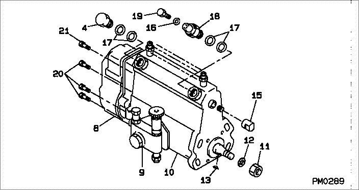
| 000. | [01] | 19000-00870 | PUMP ASSY, INJECTI | 01707840 |
| 004. | [01] | 94918-00310 | SCREW, HOLLOW | 21702980 |
| 008. | [01] | 09080-04800 | GOVERNOR ASSY, MEC | |
| 009. | [01] | 09210-00980 | PUMP ASSY, FUEL FE | |
| 010. | [01] | 09010-03340 | BODY ASSY, INJECTI | |
| 011. | [01] | 94905-02450 | NUT, HEXAGON | 21703380 |
| 012. | [01] | 94901-50500 | WASHER, SPRING | 21703370 |
| 013. | [01] | 94913-00050 | KEY, WOODRUFF | 21703900 |
| 015. | [01] | 09001-80140 | COVER, CONTROL RAC | 21703400 |
| 016. | [01] | 94901-81020 | WASHER, COPPER PLA | 21706370 |
| 017. | [04] | 09022-20050 | WASHER, FUEL PIPE | |
| 018. | [01] | 09031-00011 | VALVE ASSY, OVERFL | 21701340 |
| 019. | [01] | 09024-40080 | SCREW, AIR BLEEDER | 21704700 |
| 020. | [06] | 94900-50191 | SCREW, SLOTTED FLA | |
| 021. | [01] | 91518-08221 | BOLT, W/WASHER |
Include in #3:
19000-00870
as PUMP ASSY, INJECTI
Cross reference number
| Part num | Firm num | Firm | Name |
| 19000-00870 | 01707840 | PUMP ASSY, INJECTI | |
| 01707840 | MITSUI DEUTZ | PUMP ASSY, INJECTI |
Information:
Schematic Of Fuel System
(1) Fuel priming pump (closed position). (2) Fuel priming pump (open position). (3) Return line for constant bleed valve. (4) Constant bleed valve. (5) Manual bleed valve. (6) Fuel injection nozzle. (7) Fuel tank. (8) Fuel inlet line. (9) Fuel filter. (10) Fuel line to injection pump. (11) Fuel transfer pump. (12) Fuel bypass valve. (13) Camshaft. (14) Housing for fuel injection pumps. (A) Check valve. (B) Check valve. (C) Check valve. (D) Check valve. (F) Water Separator.
Diesel fuel is the only lubrication for the moving parts in the transfer pump, injection pump housing and the governor. The injection pump housing must be full of fuel before turning the camshaft.
This fuel system has governor weights, a thrust collar and two governor springs. One governor spring is for high idle and the other governor spring is for low idle. Rotation of the shaft for governor control, compression of the governor springs, movement of connecting linkage in the governor and injection pump housing controls the amount of fuel sent to the engine cylinders.Fuel from fuel tank (7) is pulled by fuel transfer pump (11) through water separator (F) (if so equipped) and fuel filter (9). From fuel filter (9) the fuel goes to housing for fuel injection pumps (14). The fuel goes in housing (14) at the top and goes through inside passage (20) to fuel transfer pump (11).
Cross Section Of Fuel System With Dashpot Governor
(11) Fuel transfer pump. (13) Camshaft. (14) Housing for fuel injection pumps. (15) Lever. (16) Governor housing. (17) Load stop pin. (18) Cover. (19) Sleeve control shafts (two). (20) Inside fuel passage. (21) Drive gear for fuel transfer pump. (22) Lever on governor shaft. (23) Piston for dashpot governor. (24) Spring for dashpot governor. (25) Governor springs (inner spring is for low idle: outer spring is for high idle). (26) Spring seat. (27) Over fueling spring. (28) Thrust collar. (29) Load stop lever. (30) Carrier and governor weights. (31) Sleeve levers. (E) Orifice for dashpot.From fuel transfer pump (11), fuel under pressure, fills the housing for the fuel injection pumps (14). Pressure of the fuel in housing (14) is controlled by bypass valve (12). Pressure of the fuel at FULL LOAD is 205 35 kPa (30 5 psi). If the pressure of fuel in housing (14) gets too high, bypass valve (12) will move (open) to let some of the fuel return to the inlet of fuel transfer pump (11).Lever (15) for the governor is connected by linkage and governor springs (25) to the sleeve control shafts (19). Any movement of lever (22) will cause a change in the position of sleeve control shafts (19).When lever (15) is moved to give more fuel to the engine, lever (22) will put governor springs (25) in compression and move thrust collar (28) forward. As thrust collar (28) moves forward, the connecting linkage will cause sleeve control shafts (19) to turn. With this movement of the sleeve control shafts, levers (31) will lift