Information pump assy, injecti
Rating:
Components :
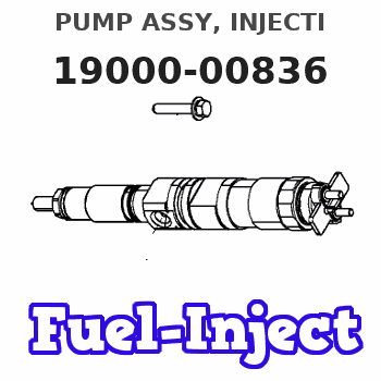
| 001. | PUMP ASSY, INJECTI | 19000-00836 |
| 002. | BODY ASSY, INJECTI | 09010-03244 |
| 003. | TIMER ASSY, AUTOMA | 09180-01150 |
| 004. | PUMP ASSY, FUEL FE | 09210-00971 |
| 005. | COUPLING ASSY | 09240-00161 |
Scheme ###:
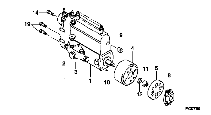
| 000. | [01] | 19000-00836 | PUMP ASSY, INJECTI | 22100-77212 |
| 001. | [01] | 09010-03244 | BODY ASSY, INJECTI | 22120-77131 |
| 002. | [01] | 09070-00072 | GOVERNOR ASSY, COM | 22320-77070 |
| 003. | [01] | 09210-00971 | PUMP ASSY, FUEL FE | 22510-77130 |
| 004. | [01] | 09180-01150 | TIMER ASSY, AUTOMA | 22610-77050 |
| 005. | [01] | 09243-60020 | COUPLING, INJECTIO | 22632-66010 |
| 006. | [01] | 09240-00161 | COUPLING ASSY | 22630-77051 |
| 009. | [01] | 09001-80010 | COVER, CONTROL RAC | 22116-77020 |
| 010. | [01] | 94913-00050 | KEY, WOODRUFF | 90099-13002 |
| 011. | [01] | 09001-20010 | NUT, TIMER ROUND | 22611-77020 |
| 012. | [01] | 90258-12001 | WASHER, SPRING | 94511-01200 |
| 014. | [01] | 91518-08221 | BOLT, W/WASHER | 90091-20804 |
| 019. | [04] | 94904-70620 | BOLT, W/WASHER | 90099-04526 |
Include in #3:
19000-00836
as PUMP ASSY, INJECTI
Cross reference number
| Part num | Firm num | Firm | Name |
| 19000-00836 | 22100-7721 | PUMP ASSY, INJECTI |
Information:
Turbocharger
Start By:a. remove turbocharger 1. Install the turbocharger on Tool (A).2. Put alignment marks on the two housings and cartridge assembly of the turbocharger for correct alignment during assembly.3. Loosen clamp (3), and remove compressor housing (4) from cartridge assembly (2).4. Loosen the remaining clamp, and remove cartridge assembly (2) from turbine housing (1).
Typical Example5. Put the cartridge group (shown in the illustration) with nut (16) up in Tool (B). Use a 5S9566 Sliding T-Wrench and a universal socket to remove nut (16) that holds the compressor wheel (15) to the wheel assembly (19).6. Remove compressor wheel (15) and housing assembly (6) from wheel assembly (19). Remove piston ring (13) from the wheel assembly.7. Use Tool (C), and remove snap ring (5) from housing assembly (6). Remove insert (14) and sleeve (18) from the housing assembly. Remove seal (22) from insert (14). Remove ring (20) from sleeve (18).8. Remove oil deflector (23), thrust ring (21), bearing assembly (7), spacer sleeve (24) and thrust ring (8) from housing assembly (6).9. Use Tool (D), and remove snap ring (9) from the housing assembly. Remove bearing (25). Remove snap ring (10) with Tool (D).10. Use Tool (D), and remove snap ring (12) from the housing assembly. Remove bearing (26). Remove snap ring (11) with Tool (D).11. Check all the parts of the turbocharger for damage. If any parts are damaged, use new parts for replacement. See Special Instruction Form No. SMHS6854 for turbocharger reconditioning. Also, see Guidelines For Reusable Parts, Form No. SEBF8018. The following steps are for assembly of the turbocharger.12. Make sure that all the oil passages in the turbocharger cartridge housing are clean and free of dirt and foreign material. Do not put oil on any parts of the turbocharger until after the compressor wheel has been installed. After the turbocharger has been assembled, put clean engine oil into the oil inlet of the turbocharger.
Make sure the snap rings that hold bearings (25) and (26) in housing assembly (6) are installed with the round edge of the outside diameter toward the bearing.
13. Install snap ring (11) with Tool (D). Install bearing (26). Install snap ring (12) with Tool (D).14. Install snap ring (10) with Tool (D). Install bearing (25). Install snap ring (9) with Tool (D).15. Put wheel assembly (19) in position on Tool (B) with the threaded portion end up. Put 6V2055 High Vacuum Grease in the groove for piston ring (13) at assembly to one half or more of the depth of the groove all the way around.16. Install piston ring (13) in the groove in wheel assembly (19).17. Put housing assembly (6) in position on wheel assembly (19).18. Install thrust ring (8) and spacer sleeve (24) on wheel assembly (19).19. Make sure the screen is in place in bearing assembly (7). Install bearing assembly (7) over spacer sleeve (24). Make sure the screen in the bearing assembly is facing toward housing assembly (6) when it is installed.20. Install thrust ring (21) and oil deflector (23)