Information pump assy, injecti
Rating:
Components :
| 001. | PUMP ASSY, INJECTI | 19000-00603 |
| 002. | BODY ASSY, INJECTI | 09010-03220 |
| 003. | GOVERNOR ASSY, MEC | 09080-04334 |
| 004. | GOVERNOR ASSY, MEC | 09080-04772 |
| 005. | PUMP ASSY, FUEL FE | 09210-00073 |
Scheme ###:
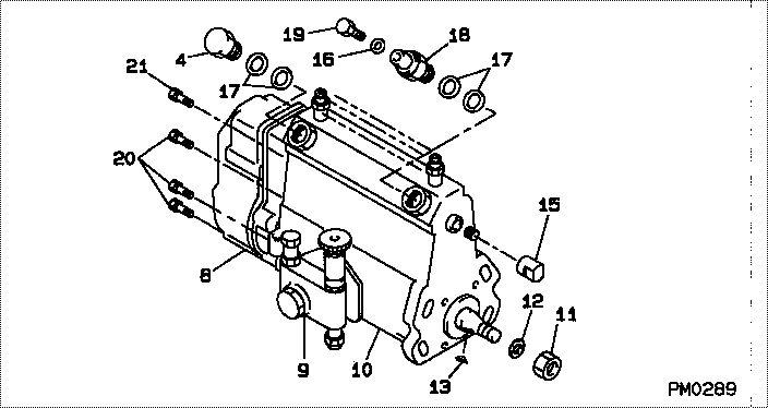
| 000. | [01] | 19000-00603 | PUMP ASSY, INJECTI | 01707674 |
| 004. | [01] | 94918-00310 | SCREW, HOLLOW | 21702980 |
| 008. | [01] | 09080-04772 | GOVERNOR ASSY, MEC | 21706400 |
| 008. | [01] | 09080-04334 | GOVERNOR ASSY, MEC | 21706430 |
| 009. | [01] | 09210-00073 | PUMP ASSY, FUEL FE | 02001312 |
| 010. | [01] | 09010-03220 | BODY ASSY, INJECTI | 21706440 |
| 011. | [01] | 94905-02450 | NUT, HEXAGON | 21703380 |
| 012. | [01] | 94901-50500 | WASHER, SPRING | 21703370 |
| 013. | [01] | 94913-00190 | KEY, WOODRUFF | |
| 015. | [01] | 09001-80140 | COVER, CONTROL RAC | 21703400 |
| 016. | [01] | 94901-81020 | WASHER, COPPER PLA | 21706370 |
| 017. | [04] | 09022-20011 | WASHER, FUEL PIPE | 21703000 |
| 017. | [04] | 09022-20070 | WASHER, FUEL PIPE | |
| 018. | [01] | 09031-00011 | VALVE ASSY, OVERFL | 21701340 |
| 019. | [01] | 09024-40080 | SCREW, AIR BLEEDER | 21704700 |
| 020. | [06] | 91518-06161 | BOLT, W/WASHER | |
| 021. | [01] | 91518-08221 | BOLT, W/WASHER |
Include in #3:
19000-00603
as PUMP ASSY, INJECTI
Cross reference number
| Part num | Firm num | Firm | Name |
| 19000-00603 | 01707674 | PUMP ASSY, INJECTI |
Information:
TIMING MARKS2. Remove the plug from the timing pin hole in fuel injection pump housing and install timing pin (1).
TIMING PIN INSTALLED
1. FT887 Timing Pin (Fabricated Tool).3. Remove bolts (2) and tachometer drive assembly (3) from the fuel injection pump camshaft.
PUMP DRIVE GEAR
2. Bolts (three). 3. Tachometer drive assembly. 4. Drive gear.4. Remove the drive gear (4) from the fuel injection pump camshaft.
TIMING ADVANCE
5. Retaining screw. 6. Washer. 7. Automatic timing advance.5. Remove retaining screw (5), washer (6), and automatic timing advance (7) from the engine camshaft.6. Install puller (8), with spacer (10) over the shaft in the camshaft and spacer (9) on spacer (10) as shown and remove the gear from the camshaft.
REMOVING GEAR (Typical Example)
8. 1P2321 Puller. 9. 8S5579 Spacer. 10. 9S9155 Spacer.Install Camshaft Gear
1. Heat the gear to a temperature of approximately 400° F (204° C) before installing on the camshaft.
Do not head the gear with a torch. Do not heat the gear to a temperature of more than 600° F (315° C). Heating the gear with a torch or to a temperature of more than 600° F (315° C) may cause the two drive dowels for the automatic timing advance to loosen and come out of the gear.
TIMING MARKS2. Align slot in gear hub with the pin in the camshaft. Install the gear on the camshaft with timing mark on gear aligned with timing mark on crankshaft gear. Be sure the gear is completely seated against the shoulder of the camshaft.
Do not drive the gear on the camshaft. Serious damage can result to camshaft or camshaft thrust pin.
3. Align holes in weights with dowels in gear and install the automatic timing advance.4. Align pin (11) in washer (6) with hole (12) in camshaft and install washer (6).
INSTALLING WASHER
6. Washer. 11. Pin. 12. Hole.5. Install retaining screw (5) and tighten to 108 36 lb. in. (124.5 41.5 cm.kg). Stake screw (5) in two places.
Stake retaining screw (5) carefully. Heavy blows on washer or retaining screw can force the shaft extension too far into the camshaft and eliminate all end clearance.
STAKING SCREW (Typical Example)
5. Retaining screw.6. After retaining screw (5) is staked, the gear and weight assembly requires .003 to .027 in. (0.08 to 0.69 mm) end clearance to prevent binding against the washer, camshaft end, or camshaft gear.7. Put timing plate (14) on the engine and thread bolt (13) into the timing gear.
TIMING PLATE INSTALLED
13. Bolt. 14. 5P950 Timing Plate.8. Install drive gear (4) on the fuel injection pump camshaft with the holes in the position shown and the part number facing out. To be able to advance the timing adjustment without removing the front cover, position gear (4) in the direction of the arrow so the bolt holes in the fuel injection pump camshaft are off center as shown. The bolts must thread freely into the holes in the fuel injection pump camshaft.
GEAR INSTALLED
4. Drive gear.9. Install tachometer drive assembly (3) and tighten finger tight.10. Install bolts (2) and tighten the bolts