Information pump assy, injecti
Nozzle:
0935000550
Rating:
KIT List:
| Governor assy, mec | 1908900160 |
Components :
| 001. | PUMP ASSY, INJECTI | 19000-00130 |
| 002. | BODY ASSY, INJECTI | 09010-03070 |
| 003. | GOVERNOR ASSY, MEC | 09080-04290 |
| 004. | PUMP ASSY, FUEL FE | 09210-00531 |
| 005. | COUPLING ASSY | 09250-00103 |
Scheme ###:
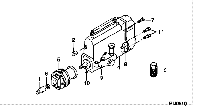
| 000. | [01] | 19000-00130 | PUMP ASSY, INJECTI | 30061-91040 |
| 001. | [01] | 09001-20010 | NUT, TIMER ROUND | 90012-0011 |
| 002. | [01] | 09001-80010 | COVER, CONTROL RAC | ME022610 |
| 003. | [01] | 09006-10011 | COVER, PRIMING PUM | ME022307 |
| 004. | [01] | 09010-03070 | BODY ASSY, INJECTI | 30061-91500 |
| 005. | [01] | 09250-00103 | COUPLING ASSY | 30061-60503 |
| 006. | [01] | 90258-12001 | WASHER, SPRING | MM500025 |
| 007. | [01] | 91518-08221 | BOLT, W/WASHER | MM500963 |
| 008. | [01] | 09080-04290 | GOVERNOR ASSY, MEC | |
| 009. | [01] | 09210-00531 | PUMP ASSY, FUEL FE | 30061-80400 |
| 010. | [01] | 94913-00190 | KEY, WOODRUFF | ME703361 |
| 011. | [06] | 94900-50191 | SCREW, SLOTTED FLA | ME022439 |
Include in #3:
19000-00130
as PUMP ASSY, INJECTI
Cross reference number
| Part num | Firm num | Firm | Name |
| 19000-00130 | 30061-9104 | PUMP ASSY, INJECTI | |
| 30061-91040 | MITSUBISHI | PUMP ASSY, INJECTI |
Information:
Remove Timing Gears
Start By:a. remove timing gear cover1. Time the engine as follows:a. Install Tool (A) in the flywheel housing.b. Remove the cover from the side of the fuel injection pump housing so the timing pin can be installed. Remove the plug from the flywheel housing so the timing bolt can be installed.c. Turn the engine in the direction of engine rotation until Tool (B) can be installed in fuel injection pump housing and located in the groove in the fuel injection pump camshaft, a 3/8" - 16 NC bolt can be installed in the flywheel through the hole in the flywheel housing, and the "C" marks on the crankshaft gear and the camshaft gear are in alignment with each other. 2. Loosen bolt (1) until there is approximately 3.18 mm (.125 in) gap between washer (2) and fuel pump drive gear (3).3. Install Tool (C) as shown, and loosen the fuel pump drive gear from the taper on the fuel injection pump camshaft. Remove Tool (C), the bolt, washer and fuel pump drive gear.4. Remove the bolts and plate (4) that hold idler gear (5) in position. Remove the idler gear. If necessary, remove the bearing from the idler gear with Tool (D) and a press.
Do not turn the crankshaft after camshaft gear (6) has been removed. Turning the crankshaft will cause damage to the valves.
5. Remove the four bolts that hold camshaft gear (6) to the camshaft. Remove the camshaft gear.Install Timing Gears
1. Make an alignment of the "C" marks on crankshaft gear (3) and camshaft gear (4). Install the camshaft gear and the bolts that hold it. Tighten the bolts to a torque of 55 7 N m (41 5 lb ft).2. Install the bearing in idler gear (1) with Tool (A). The end of the bearing must be 1.52 mm (.060 in) below the face of the gear hub after installation.3. Be sure the oil hole in the shaft for idler gear (1) is open. Put idler gear (1) and plate (2) in position on the shaft. Install the bolts that hold them. 4. Make sure Tool (C) is in position in the groove of the fuel injection pump camshaft.5. Put fuel injection pump drive gear (5) in position on the fuel injection pump camshaft. Put washer (6) in position on the gear with the largest diameter toward the front of the engine. Install bolt (7), and tighten it to a torque of 7 N m (5 lb ft). Make sure bolt (7) does not turn while the flywheel is being turned.6. Remove the timing bolt from the flywheel, and use Tool (B) to turn the flywheel in the opposite direction of engine rotation. Turn the flywheel until the "C" mark on the crankshaft gear moves 30°.7. Turn the flywheel in the direction of engine rotation until the timing bolt can be installed in the flywheel and the "C" marks are in alignment. This will remove all of the backlash from the