Information pump assy, fuel su
Rating:
Components :
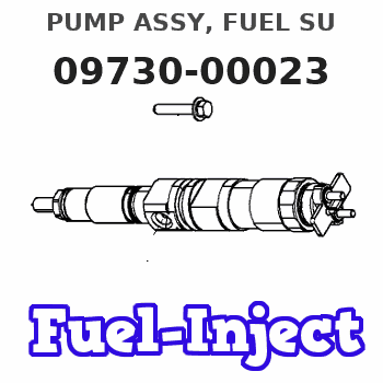
| 001. | PUMP ASSY, FUEL SU | 09730-00023 |
| 001. | PUMP ASSY, FUEL SU | 09730-00023 |
| 002. | OVERHAUL KIT, SUPP | 09749-00010 |
Scheme ###:
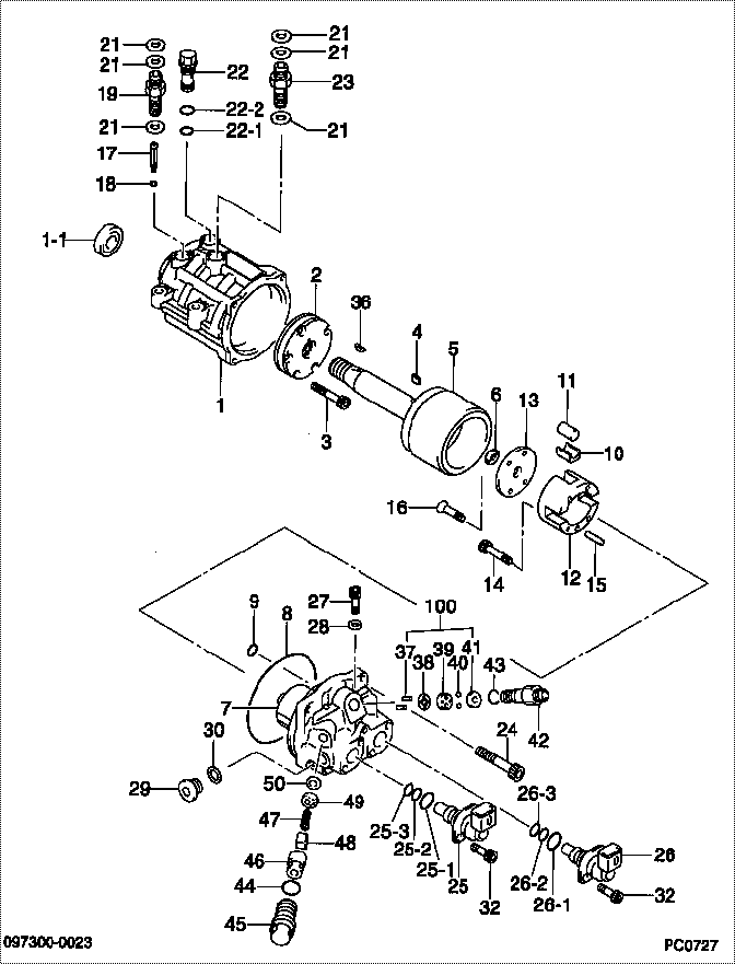
| 000. | [01] | 09730-00023 | PUMP ASSY, FUEL SU | 8-97228919-4 |
| 000. | [01] | 09730-00024 | PUMP ASSY, FUEL SU | 8-97228919-5 |
| 001. | [01] | 09731-00022 | HOUSING SUB-ASSY, | |
| 001-001. | [01] | 09739-70010 | SEAL, OIL, HOUSING | |
| 002. | [01] | 09734-00020 | PUMP SUB-ASSY, FUE | |
| 003. | [05] | 09807-60010 | BOLT, DISTRIBUTIVE | |
| 004. | [01] | 09749-10010 | KEY SET, FEED PUMP | |
| 005. | [01] | 09733-00050 | CAMSHAFT SUB-ASSY, | |
| 006. | [1C] | 09733-60030 | WASHER, CAMSHAFT | |
| 006. | [1C] | 09733-60020 | WASHER, CAMSHAFT | |
| 006. | [1C] | 09733-60010 | WASHER, CAMSHAFT | |
| 007. | [01] | 09740-00032 | HEAD SUB-ASSY, SUP | |
| 008. | [01] | 09739-60040 | O-RING, SUPPLY PUM | |
| 009. | [01] | 09739-60010 | O-RING, SUPPLY PUM | |
| 010. | [04] | 09738-00050 | SHOE | |
| 011. | [4C] | 09738-50040 | ROLLER | |
| 011. | [4C] | 09738-50030 | ROLLER | |
| 012. | [01] | 09740-50012 | GUIDE, SHOE | |
| 013. | [01] | 09740-50020 | GUIDE, SHOE | |
| 014. | [04] | 09739-80010 | BOLT, SUPPLY PUMP | |
| 015. | [01] | 90422-05101 | PIN, PARALLEL | |
| 016. | [04] | 91060-04101 | SCREW, CROSSRECESS | |
| 017. | [01] | 09737-00010 | FILTER SUB-ASSY | |
| 018. | [01] | 09604-90460 | O-RING | |
| 019. | [01] | 09602-10190 | SCREW, OVERFLOW | 8-97261353-0 |
| 021. | [06] | 09024-10010 | WASHER, AIR BLEEDE | 8-97141182-0 |
| 022. | [01] | 09736-00011 | VALVE SUB-ASSY, RE | |
| 022-001. | [01] | 09806-60030 | O-RING, DISTRIBUTI | |
| 022-002. | [01] | 09806-60020 | O-RING, DISTRIBUTI | |
| 023. | [01] | 09732-10040 | SCREW, OVERFLOW | |
| 024. | [04] | 09644-90050 | BOLT, SOCKET | |
| 025. | [01] | 09671-00014 | VALVE ASSY, SUCTIO | |
| 025-001. | [01] | 09604-90530 | O-RING | |
| 025-002. | [01] | 09604-90640 | O-RING | |
| 025-003. | [01] | 09739-90010 | RING, BACKUP | |
| 026. | [01] | 09671-00024 | VALVE ASSY, SUCTIO | |
| 026-001. | [01] | 09604-90530 | O-RING | |
| 026-002. | [01] | 09604-90640 | O-RING | |
| 026-003. | [01] | 09739-90010 | RING, BACKUP | |
| 027. | [02] | 09747-50020 | PLUG | |
| 028. | [02] | 94901-81030 | WASHER, COPPER PLA | |
| 029. | [01] | 09031-70060 | PLUG, SCREW | |
| 030. | [01] | 09806-50020 | GASKET | |
| 032. | [04] | 09739-80020 | BOLT, SUPPLY PUMP | |
| 036. | [01] | 09749-20010 | KEY SET, WOODRUFF | |
| 037. | [01] | 09746-90010 | PIN, STOPPER | |
| 038. | [01] | 09746-60011 | GASKET, DELIVERY V | |
| 039. | [01] | 09745-10010 | SEAT, DELIVERY VAL | |
| 040. | [02] | 09745-30010 | VALVE, DELIVERY | |
| 041. | [01] | 09745-50011 | STOPPER, DELIVERY | |
| 042. | [01] | 09746-50011 | HOLDER, DELIVERY V | |
| 043. | [01] | 09739-60021 | O-RING, SUPPLY PUM | |
| 044. | [02] | 09739-60031 | O-RING, SUPPLY PUM | |
| 045. | [02] | 09747-50011 | PLUG | |
| 046. | [02] | 09747-10010 | GUIDE, FUEL FEED V | |
| 047. | [02] | 09747-70010 | SPRING | |
| 048. | [02] | 09747-30010 | VALVE, FUEL FEED | |
| 049. | [02] | 09747-80012 | STOPPER, FUEL FEED | |
| 050. | [02] | 09747-60011 | GASKET | |
| 100. | [01] | 09749-30010 | VALVE KIT, SUPPLY | |
| 200. | [01] | 09749-00010 | OVERHAUL KIT, SUPP |
Include in #3:
09730-00023
as PUMP ASSY, FUEL SU
Cross reference number
| Part num | Firm num | Firm | Name |
| 09730-00023 | 8-97228919 | PUMP ASSY, FUEL SU |
Information:
start by:a) remove valve cover 1. Use tool (A) to disconnect fuel line assemblies (1) from the fuel injection valves and valve base adapters. Remove fuel line assemblies (1). 2. Remove push rods (2) with tool (B). 3. Remove valve bridges (3) from the bridge dowels. 4. Remove the nuts that hold the fuel injection valve assemblies in place. Use tool (C) to remove fuel injection valves (4) from the direct injection adapters. 5. Use tool (D) to remove direct injection adapters (5) and gaskets from the cylinder heads.Install Direct Injection Adapters
1. Put 5P3931 Anti-Seize Compound on the threads of direct injection adapters (1).2. Put liquid soap on O-ring seal (3) and the adapter bore in the cylinder head. Install O-ring seal (3) on the adapter.3. Install adapter (1) and gasket (2) in the cylinder head. Use tool (A) to tighten the adapter to a torque of 150 10 lb.ft. (205 14 N m). 4. Put a small amount of clean engine oil on the bridge dowels. Install valve bridges (4). 5. Put a small amount of diesel fuel in the direct injection adapter bore. Install fuel injection valves (5) with tool (B). Tighten the nuts that hold the injection valves in place to a torque of 55 5 lb.ft. (75 7 N m). 6. Install push rods (9) with tool (C).7. Put a small amount of diesel fuel on O-ring seal (6) and install fuel line assemblies (8). Tighten fuel line nuts (7) to a torque of 30 5 lb.ft. (40 7 N m) with tool (D).end by:a) install valve covers
1. Put 5P3931 Anti-Seize Compound on the threads of direct injection adapters (1).2. Put liquid soap on O-ring seal (3) and the adapter bore in the cylinder head. Install O-ring seal (3) on the adapter.3. Install adapter (1) and gasket (2) in the cylinder head. Use tool (A) to tighten the adapter to a torque of 150 10 lb.ft. (205 14 N m). 4. Put a small amount of clean engine oil on the bridge dowels. Install valve bridges (4). 5. Put a small amount of diesel fuel in the direct injection adapter bore. Install fuel injection valves (5) with tool (B). Tighten the nuts that hold the injection valves in place to a torque of 55 5 lb.ft. (75 7 N m). 6. Install push rods (9) with tool (C).7. Put a small amount of diesel fuel on O-ring seal (6) and install fuel line assemblies (8). Tighten fuel line nuts (7) to a torque of 30 5 lb.ft. (40 7 N m) with tool (D).end by:a) install valve covers