Information compensator sub-as
Rating:
Scheme ###:
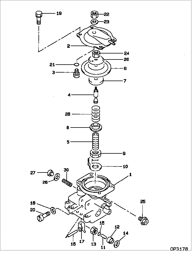
| 000. | [01] | 09649-01590 | COMPENSATOR SUB-AS | 22540-1C130 |
| 001. | [01] | 09644-01710 | COVER SUB-ASSY, GO | 22703-1C120 |
| 002. | [01] | 09644-01320 | COVER SUB-ASSY, GO | 22703-17140 |
| 003. | [01] | 09621-60030 | STOPPER, TIMER SLI | 22658-64518 |
| 004. | [01] | 09646-50800 | R0D, PUSH | 22321-17420 |
| 005. | [01] | 09611-80160 | BUSHING, GUIDE | 22348-64360 |
| 006. | [01] | 19263-10010 | DIAPHRAGM | 22542-54260 |
| 007. | [01] | 09624-60020 | SHEET, PLUNGER SPR | 22143-54260 |
| 008. | [01] | 09611-80190 | BUSHING, GUIDE | 22348-54490 |
| 009. | [01] | 94905-04070 | NUT, HEXAGON | 90099-05156 |
| 010. | [01] | 09621-10070 | CLIP, TIMER | 22656-54490 |
| 011. | [01] | 09645-50090 | PIN, LEVER CONECTI | 22338-54120 |
| 012. | [01] | 09611-80020 | BUSHING, GUIDE | 22348-54121 |
| 013. | [01] | 09625-40021 | NUT, GOVERNOR SHAF | 22722-54120 |
| 014. | [01] | 94901-81680 | WASHER, COPPER PLA | 90099-01473 |
| 015. | [01] | 09604-90230 | O-RING | 22193-55031 |
| 016. | [01] | 09627-20040 | PIN, LEVER SUPPORT | 22526-54120 |
| 017. | [01] | 09629-50680 | LEVER SUB-ASSY, CO | 22308-17570 |
| 017. | [01] | 09629-50080 | LEVER SUB-ASSY, CO | 22308-54140 |
| 018. | [02] | 09642-60110 | GASKET, DELIVERY V | 22149-6D450 |
| 019. | [04] | 09644-90130 | BOLT, SOCKET | 22395-54263 |
| 020. | [02] | 09626-90032 | BOLT, GOVERNOR LIN | 22739-54120 |
| 021. | [01] | 09604-90180 | O-RING | 22193-54561 |
| 022. | [01] | 94905-04100 | NUT, HEXAGON | 90099-05181 |
| 022. | [01] | 94905-05430 | NUT, HEXAGON | 90099-05252 |
| 023. | [01] | 90200-08211 | WASHER, PLATE | 90093-00802 |
| 024. | [01] | 90176-06361 | NUT, HEXAGON | 90092-20608 |
| 025. | [01] | 09602-00110 | SCREW SUB-ASSY, OV | 22160-54262 |
| 026. | [01] | 09642-60120 | GASKET, DELIVERY V | 22149-54800 |
| 027. | [01] | 09031-70240 | PLUG, SCREW | 22129-55110 |
| 028. | [1C] | 09649-20040 | SPRING, BOOST COMP | 22546-54260 |
| 028. | [1C] | 09649-20111 | SPRING, BOOST COMP | 22546-17420 |
| 028. | [1C] | 09649-20121 | SPRING, BOOST COMP | 22546-64360 |
| 028. | [1C] | 09649-20130 | SPRING, BOOST COMP | 22546-58790 |
| 029. | [01] | 19263-30010 | WASHER, THRUST | 22549-17140 |
| 030. | [01] | 09646-60090 | SPRING | 22327-55030 |
Include in #3:
09649-01590
as COMPENSATOR SUB-AS
Cross reference number
| Part num | Firm num | Firm | Name |
| 09649-01590 | 22540-1C13 | COMPENSATOR SUB-AS | |
| 22540-1C130 | TOYOTA | COMPENSATOR SUB-AS |
Information:
Introduction
On the machines listed above, the Delayed Engine Shutdown (DES) feature delays the engine from shutting off until the Diesel Exhaust Fluid (DEF) injector has cooled. Installing the DEF phase change tank decreases the frequency of the DES feature activating.Safety Section
Do not perform any procedure in this Special Instruction until you have read the information and you understand the information.
Care must be taken to ensure that fluids are contained during performance of inspection, maintenance, testing, adjusting, and repair of the product. Be prepared to collect the fluid with suitable containers before opening any compartment or disassembling any component containing fluids.Refer to Special Publication, NENG2500, "Dealer Service Tool Catalog" for tools and supplies suitable to collect and contain fluids on Cat® products.Dispose of all fluids according to local regulations and mandates.
Accidental engine starting can cause injury or death to personnel working on the equipment.To avoid accidental engine starting, disconnect the battery cable from the negative (−) battery terminal. Completely tape all metal surfaces of the disconnected battery cable end in order to prevent contact with other metal surfaces which could activate the engine electrical system.Place a Do Not Operate tag at the Start/Stop switch location to inform personnel that the equipment is being worked on.
Required Parts
Table 1
Required Parts
Item Qty Part Number Part Name
3 1 5I-3822 Plate
5 1 467-9635 Hose
6 6 428-8808 Hose Clamp
7 1 418-2057 Hose
8 1 467-9634 Hose
9 1 5P-4924 Elbow
10 1 6V-3250 O-Ring Seal
11 1 424-1209 Tank
12 2 326-4516 Cable Tie
13 1 454-4235 Plate
14 1 511-8273 Sheet As
15 1 467-9640 Plate As
16 3 8T-4136 Bolt
17 3 8T-4121 Hard Washer
18 2 8T-4189 Bolt
19 2 8T-4224 Hard Washer Installation Procedure
Illustration 1 g06124125
Remove plate (1) and discard. Save the hardware and hook assembly (2) for reuse.
Illustration 2 g06124137
(3) 5I-3822 Plate
Weld plate (3) in the location specified in Illustration 2.
Illustration 3 g06124150
Remove two hoses (4).
Illustration 4 g06124157
(5) 467-9635 Hose
(6) 428-8808 Hose Clamp
(7) 418-2057 Hose
(8) 467-9634 Hose
(9) 5P-4924 Elbow
(10) 6V-3250 O-Ring Seal
(11) 424-1209 Tank
Install hose (7) and two hose clamps (6). Slowly tighten the clamps to 6.6 0.2 N m (58 1.8 lb in).
Install one end of hose (5) on the coolant tube and the other on tank (11). Secure the hose using two hose clamps (6). Slowly tighten the clamps to 6.6 0.2 N m (58 1.8 lb in).
Install elbow (9) and O-ring (10) onto tank (11). Tighten the elbow to 28 4 N m (21 3 lb ft).
Install hose (8) as shown using two hose clamps (6). Slowly tighten the clamps to 6.6 0.2 N m (58 1.8 lb in). Ensure the hoses connected to the tank are in parallel as shown in view D-D