Information compensator sub-as
Rating:
Scheme ###:
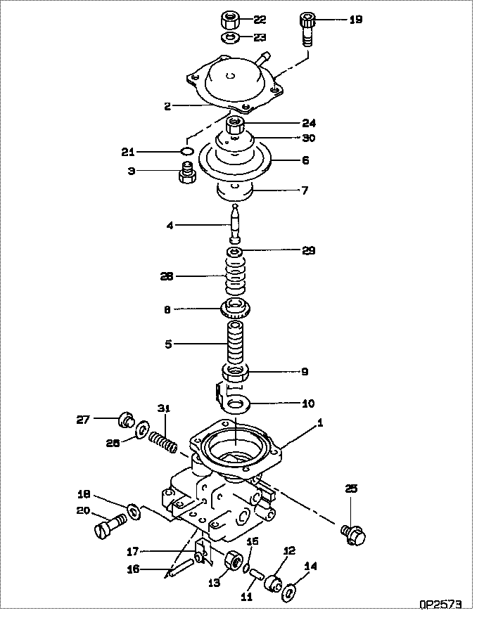
| 000. | [01] | 09649-01350 | COMPENSATOR SUB-AS | |
| 001. | [01] | 09644-01580 | COVER SUB-ASSY, GO | |
| 002. | [01] | 09644-00860 | COVER SUB-ASSY, GO | |
| 003. | [01] | 09621-60030 | STOPPER, TIMER SLI | |
| 004. | [01] | 09646-50760 | R0D, PUSH | |
| 005. | [01] | 09611-80160 | BUSHING, GUIDE | |
| 006. | [01] | 19263-10010 | DIAPHRAGM | |
| 007. | [01] | 09624-60020 | SHEET, PLUNGER SPR | |
| 008. | [01] | 09611-80190 | BUSHING, GUIDE | |
| 009. | [01] | 94905-04070 | NUT, HEXAGON | |
| 010. | [01] | 09621-10070 | CLIP, TIMER | |
| 011. | [01] | 09645-50090 | PIN, LEVER CONECTI | |
| 012. | [01] | 09611-80020 | BUSHING, GUIDE | |
| 013. | [01] | 09625-40021 | NUT, GOVERNOR SHAF | |
| 014. | [01] | 94901-81680 | WASHER, COPPER PLA | |
| 015. | [01] | 09604-90230 | O-RING | |
| 016. | [01] | 09627-20040 | PIN, LEVER SUPPORT | |
| 017. | [01] | 09629-50080 | LEVER SUB-ASSY, CO | |
| 017. | [01] | 09629-50680 | LEVER SUB-ASSY, CO | |
| 018. | [02] | 09642-60110 | GASKET, DELIVERY V | |
| 019. | [04] | 09644-90130 | BOLT, SOCKET | |
| 020. | [02] | 09626-90032 | BOLT, GOVERNOR LIN | |
| 021. | [01] | 09604-90180 | O-RING | S501 24 271 |
| 022. | [01] | 94905-04100 | NUT, HEXAGON | |
| 022. | [01] | 94905-05430 | NUT, HEXAGON | S501 24 195 |
| 023. | [01] | 90200-08211 | WASHER, PLATE | S501 24 194 |
| 024. | [01] | 90176-06361 | NUT, HEXAGON | |
| 025. | [01] | 09602-00110 | SCREW SUB-ASSY, OV | |
| 026. | [01] | 09024-10010 | WASHER, AIR BLEEDE | S501 24 283 |
| 026. | [01] | 09642-60120 | GASKET, DELIVERY V | |
| 027. | [01] | 09031-70240 | PLUG, SCREW | |
| 028. | [1C] | 09649-20040 | SPRING, BOOST COMP | |
| 028. | [1C] | 09649-20070 | SPRING, BOOST COMP | |
| 028. | [1C] | 09649-20130 | SPRING, BOOST COMP | |
| 029. | [1C] | 09649-30010 | SHIM, BOOST COMPEN | |
| 029. | [1C] | 09649-30020 | SHIM, BOOST COMPEN | |
| 029. | [1C] | 09649-30030 | SHIM, BOOST COMPEN | |
| 029. | [1C] | 09649-30040 | SHIM, BOOST COMPEN | |
| 030. | [01] | 19263-30010 | WASHER, THRUST | |
| 031. | [01] | 09646-60090 | SPRING |
Include in #3:
09600-09860
as COMPENSATOR SUB-AS
09649-01350
Cross reference number
| Part num | Firm num | Firm | Name |
| 09649-01350 | COMPENSATOR SUB-AS |
Information:
Start By:a. remove valve cover 1. Disconnect fuel line nut (1). Remove nut (2) and O-ring seal. Disconnect fuel line nut (4) and remove fuel line assembly (3).
Put protection caps on all fuel line openings.
2. Remove retainer (5) from fuel adapter with Tool (B). 3. Install Tooling (C) and remove fuel nozzle assembly from adapter. 4. Install Tool (D) and remove adapter (6). 5. Remove carbon seal stop (7) with Tool (E). 6. Remove washer (8) and bleed screw (9) from fuel nozzle assembly (10). The following steps are for the installation of the fuel injection nozzles and adapters. 7. Install new carbon seal stop (7) with Tool (E). 8. Make sure the correct washer (8) is used when the nozzle assembly (10) is installed. Always use a new washer anytime the bleed screw (9) is loosened or removed. Install fuel nozzle assembly (10) in adapter (6). Install retainer (5) to a torque of 48 7 N m (35 5 lb ft). 9. Put 5P-3931 Anti-Seize Compound on the threads of the adapter before installation. Install fuel adapter (6) with Tool (D). Torque for the adapter is 200 14 N m (150 10 lb ft).10. Install fuel injection line assembly (3) (finger tighten connections first). Install the O-ring seal and nut (2) to a torque of 30 7 N m (22 5 lb ft). Reconnect fuel line nut (1) to a torque of 40 7 N m (30 5 lb ft). Use Tool (A) to reconnect fuel line nut (4) to a torque of 40 7 N m (30 5 lb ft).End By:a. install valve cover