Information compensator sub-as
Rating:
Scheme ###:
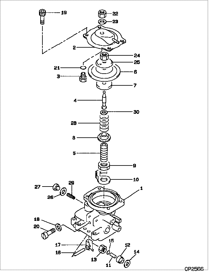
| 000. | [01] | 09649-01060 | COMPENSATOR SUB-AS | 22540-17560 |
| 001. | [01] | 09644-00664 | COVER SUB-ASSY, GO | 22703-64850 |
| 002. | [01] | 09644-01320 | COVER SUB-ASSY, GO | 22703-17140 |
| 003. | [01] | 09621-60030 | STOPPER, TIMER SLI | 22658-64518 |
| 004. | [01] | 09646-50450 | R0D, PUSH | 22321-17190 |
| 004. | [01] | 09646-50760 | R0D, PUSH | |
| 005. | [01] | 09611-80160 | BUSHING, GUIDE | 22348-64360 |
| 006. | [01] | 19263-10010 | DIAPHRAGM | 22542-54260 |
| 007. | [01] | 09624-60020 | SHEET, PLUNGER SPR | 22143-54260 |
| 008. | [01] | 09611-80190 | BUSHING, GUIDE | 22348-54490 |
| 009. | [01] | 94905-04070 | NUT, HEXAGON | 90099-05156 |
| 010. | [01] | 09621-10070 | CLIP, TIMER | 22656-54490 |
| 011. | [01] | 09645-50090 | PIN, LEVER CONECTI | 22338-54120 |
| 012. | [01] | 09611-80020 | BUSHING, GUIDE | 22348-54121 |
| 013. | [01] | 09625-40021 | NUT, GOVERNOR SHAF | 22722-54120 |
| 014. | [01] | 94901-81680 | WASHER, COPPER PLA | 90099-01473 |
| 015. | [01] | 09604-90230 | O-RING | 22193-55031 |
| 016. | [01] | 09627-20040 | PIN, LEVER SUPPORT | 22526-54120 |
| 017. | [01] | 09629-50080 | LEVER SUB-ASSY, CO | 22308-54140 |
| 017. | [01] | 09629-50680 | LEVER SUB-ASSY, CO | 22308-17570 |
| 018. | [02] | 09024-80010 | WASHER, DRAIN SCRE | 22378-76010 |
| 018. | [02] | 09642-60110 | GASKET, DELIVERY V | 22149-6D450 |
| 019. | [04] | 09644-90130 | BOLT, SOCKET | 22395-54263 |
| 020. | [02] | 09626-90032 | BOLT, GOVERNOR LIN | 22739-54120 |
| 021. | [01] | 09604-90180 | O-RING | 22193-54561 |
| 022. | [01] | 94905-04100 | NUT, HEXAGON | 90099-05181 |
| 022. | [01] | 94905-05430 | NUT, HEXAGON | 90099-05252 |
| 023. | [01] | 90200-08211 | WASHER, PLATE | 90093-00802 |
| 024. | [01] | 90176-06361 | NUT, HEXAGON | 90092-20608 |
| 025. | [01] | 19263-30010 | WASHER, THRUST | 22549-17140 |
| 026. | [01] | 09024-10010 | WASHER, AIR BLEEDE | 22119-77020 |
| 026. | [01] | 09642-60120 | GASKET, DELIVERY V | 22149-54800 |
| 027. | [01] | 09031-70240 | PLUG, SCREW | 22129-55110 |
| 027. | [01] | 09031-70240 | PLUG, SCREW | 22129-55110 |
| 028. | [1C] | 09649-20441 | SPRING, BOOST COMP | 22546-17160 |
| 028. | [1C] | 09649-20480 | SPRING, BOOST COMP | 22546-17164 |
| 028. | [1C] | 09649-20470 | SPRING, BOOST COMP | 22546-17163 |
| 028. | [1C] | 09649-20461 | SPRING, BOOST COMP | 22546-17162 |
| 028. | [1C] | 09649-20451 | SPRING, BOOST COMP | 22546-17161 |
| 028. | [1C] | 09649-20170 | SPRING, BOOST COMP | 22546-54492 |
| 028. | [1C] | 09649-20140 | SPRING, BOOST COMP | 22546-64520 |
| 029. | [01] | 09646-60090 | SPRING | 22327-55030 |
| 030. | [1C] | 09649-30210 | SHIM, BOOST COMPEN | 22547-54491 |
| 030. | [1C] | 09649-30220 | SHIM, BOOST COMPEN | 22547-54492 |
| 030. | [1C] | 09649-30230 | SHIM, BOOST COMPEN | 22547-54493 |
| 030. | [1C] | 09649-30240 | SHIM, BOOST COMPEN | 22547-54494 |
| 030. | [1C] | 09649-30010 | SHIM, BOOST COMPEN | 22547-54260 |
| 030. | [1C] | 09649-30020 | SHIM, BOOST COMPEN | 22547-54261 |
| 030. | [1C] | 09649-30120 | SHIM, BOOST COMPEN | 22547-54267 |
| 030. | [1C] | 09649-30110 | SHIM, BOOST COMPEN | 22547-54266 |
| 030. | [1C] | 09649-30100 | SHIM, BOOST COMPEN | 22547-54265 |
| 030. | [1C] | 09649-30090 | SHIM, BOOST COMPEN | 22547-54490 |
| 030. | [1C] | 09649-30080 | SHIM, BOOST COMPEN | 22547-64361 |
| 030. | [1C] | 09649-30070 | SHIM, BOOST COMPEN | 22547-64360 |
| 030. | [1C] | 09649-30060 | SHIM, BOOST COMPEN | 22547-54268 |
| 030. | [1C] | 09649-30050 | SHIM, BOOST COMPEN | 22547-54264 |
| 030. | [1C] | 09649-30040 | SHIM, BOOST COMPEN | 22547-54263 |
| 030. | [1C] | 09649-30030 | SHIM, BOOST COMPEN | 22547-54262 |
Include in #3:
Cross reference number
| Part num | Firm num | Firm | Name |
| 09649-01060 | 22540-1756 | COMPENSATOR SUB-AS | |
| 22540-17560 | TOYOTA | COMPENSATOR SUB-AS |
Information:
2. Remove cover (1). 3. Move the rack until tool (A) can be installed to hold the rack in the center position. The rack must be in the center position to remove the fuel injection pumps.4. Use tool (B) to remove bushing (2). 5. Install tool (C) on the bonnet and remove the fuel injection pump. 6. Remove spacer (3) from the fuel injection pump housing. Spacers (3) are the same thickness for each fuel injection pump so they can be mixed. The fuel injection pump plungers and barrels are sets and can not be mixed.Install Fuel Injection Pumps
1. Install spacer (1) in the fuel injection pump housing. 2. Move the rack until tool (A) can be installed to hold the rack in the center position. The rack must be in the center position to install the fuel injection pumps.3. Turn the camshaft until the lobe of the camshaft is down for the pump to be installed. 4. Install tool (B) on the bonnet of the fuel injection pump. Put clean oil on O-ring seal (4) and install the O-ring seal and bushing (5) over tool (B) as shown. 5. Install the fuel injection pump in the pump housing with saw cut (slot) (3) in the gear in alignment with small pin (2) in the lifter assembly and groove (7) in the barrel in alignment with large pin (6) in the pump housing.6. Push down on tool (B) and tighten bushing (5) by hand until the bushing is even with the top of the housing. If installation of the bushing can not be made this far by hand, remove it. Remove the pump, put the parts in alignment again and install the bushing again.
If installation of pump is correct, the bushing can be tightened by hand until it is even with the face of the pump housing.
7. Remove tool (B) and install tool (C) in the bushing. Use tool (C) and a torque wrench to tighten the bushing to a torque of 165 14 N m (120 10 lb. ft.).8. Remove tools (C) and (A). Install the cover on the fuel injection pump housing.9. Install the fuel injection lines. Tighten the fuel injection line nuts to a torque of 41 7 N m (30 5 lb.ft.).Disassemble Fuel Injection Pumps
start by:a) remove fuel injection pumps
Be careful when the injection pumps are disassembled. Do not damage the surfaces of the plungers, barrels and bonnets. Any scratches will cause leakage inside the fuel injection pump. The plunger and barrel for each pump are made as a set. Do not put the plunger of one pump in the barrel of another pump. If one part has wear, install a complete new pump assembly. Be careful when the plunger is put into the bore of the barrel.
1. Pull plunger (1) and washer (5) out of barrel (3) and spring (2).2. Remove washer (5) from plunger (1).
Do not remove the gear from the plunger. The gear and plunger are assembled