Information compensator sub-as
Rating:
Scheme ###:
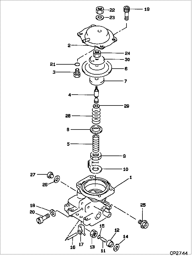
| 000. | [01] | 09649-00850 | COMPENSATOR SUB-AS | |
| 001. | [01] | 09644-00664 | COVER SUB-ASSY, GO | 22703-64850 |
| 002. | [01] | 09644-01270 | COVER SUB-ASSY, GO | 22703-5B270 |
| 002. | [01] | 09644-00860 | COVER SUB-ASSY, GO | 22703-54262 |
| 003. | [01] | 09621-60030 | STOPPER, TIMER SLI | 22658-64518 |
| 004. | [01] | 09646-50740 | R0D, PUSH | |
| 004. | [01] | 09646-50400 | R0D, PUSH | 22321-55030 |
| 005. | [01] | 09611-80160 | BUSHING, GUIDE | 22348-64360 |
| 006. | [01] | 19263-10010 | DIAPHRAGM | 22542-54260 |
| 007. | [01] | 09624-60020 | SHEET, PLUNGER SPR | 22143-54260 |
| 008. | [01] | 09611-80190 | BUSHING, GUIDE | 22348-54490 |
| 009. | [01] | 94905-04070 | NUT, HEXAGON | 90099-05156 |
| 010. | [01] | 09621-10070 | CLIP, TIMER | 22656-54490 |
| 011. | [01] | 09645-50090 | PIN, LEVER CONECTI | 22338-54120 |
| 012. | [01] | 09611-80020 | BUSHING, GUIDE | 22348-54121 |
| 013. | [01] | 09625-40021 | NUT, GOVERNOR SHAF | 22722-54120 |
| 014. | [01] | 94901-81680 | WASHER, COPPER PLA | 90099-01473 |
| 015. | [01] | 09604-90230 | O-RING | 22193-55031 |
| 016. | [01] | 09627-20040 | PIN, LEVER SUPPORT | 22526-54120 |
| 017. | [01] | 09629-50680 | LEVER SUB-ASSY, CO | 22308-17570 |
| 017. | [01] | 09629-50080 | LEVER SUB-ASSY, CO | 22308-54140 |
| 018. | [02] | 09024-80010 | WASHER, DRAIN SCRE | 22378-76010 |
| 018. | [02] | 09642-60110 | GASKET, DELIVERY V | 22149-6D450 |
| 019. | [04] | 09644-90170 | BOLT, SOCKET | 22395-5B011 |
| 019. | [04] | 09644-90130 | BOLT, SOCKET | 22395-54263 |
| 020. | [02] | 09626-90032 | BOLT, GOVERNOR LIN | 22739-54120 |
| 021. | [01] | 09604-90180 | O-RING | 22193-54561 |
| 022. | [01] | 94905-04100 | NUT, HEXAGON | 90099-05181 |
| 022. | [01] | 94905-05430 | NUT, HEXAGON | 90099-05252 |
| 023. | [01] | 90200-08211 | WASHER, PLATE | 90093-00802 |
| 024. | [01] | 90170-06361 | NUT, HEXAGON | 90092-20604 |
| 024. | [01] | 90176-06361 | NUT, HEXAGON | 90092-20608 |
| 025. | [01] | 09602-00110 | SCREW SUB-ASSY, OV | 22160-54262 |
| 026. | [01] | 09024-10010 | WASHER, AIR BLEEDE | 22119-77020 |
| 026. | [01] | 09642-60120 | GASKET, DELIVERY V | 22149-54800 |
| 027. | [01] | 09031-70130 | PLUG, SCREW | 22129-54120 |
| 028. | [1C] | 09649-20060 | SPRING, BOOST COMP | 22546-55030 |
| 028. | [1C] | 09649-20310 | SPRING, BOOST COMP | |
| 029. | [1C] | 09649-30120 | SHIM, BOOST COMPEN | 22547-54267 |
| 029. | [1C] | 09649-30110 | SHIM, BOOST COMPEN | 22547-54266 |
| 029. | [1C] | 09649-30100 | SHIM, BOOST COMPEN | 22547-54265 |
| 029. | [1C] | 09649-30090 | SHIM, BOOST COMPEN | 22547-54490 |
| 029. | [1C] | 09649-30080 | SHIM, BOOST COMPEN | 22547-64361 |
| 029. | [1C] | 09649-30070 | SHIM, BOOST COMPEN | 22547-64360 |
| 029. | [1C] | 09649-30060 | SHIM, BOOST COMPEN | 22547-54268 |
| 029. | [1C] | 09649-30050 | SHIM, BOOST COMPEN | 22547-54264 |
| 029. | [1C] | 09649-30040 | SHIM, BOOST COMPEN | 22547-54263 |
| 029. | [1C] | 09649-30030 | SHIM, BOOST COMPEN | 22547-54262 |
| 029. | [1C] | 09649-30020 | SHIM, BOOST COMPEN | 22547-54261 |
| 029. | [1C] | 09649-30010 | SHIM, BOOST COMPEN | 22547-54260 |
| 030. | [01] | 19263-30010 | WASHER, THRUST | 22549-17140 |
Include in #3:
09600-06640
as COMPENSATOR SUB-AS
09649-00850
Cross reference number
| Part num | Firm num | Firm | Name |
| 09649-00850 | COMPENSATOR SUB-AS |
Information:
Use the 8S2245 Nozzle Cleaning Tool Group, shown above, when cleaning of fuel injection nozzles is necessary. DO NOT disassemble and clean a nozzle unless testing indicates the need to do so. Always keep the work area and tools absolutely clean.
DO NOT use a steel wire brush or a wire wheel to clean the nozzle, nozzle tip or nozzle parts.
Nozzle test procedures are given in Form SEHS7292, USE OF 5P4150 NOZZLE TESTING GROUP.Troubleshooting, Cleaning and Adjustment (Pencil-Type Nozzles Only)
A. To troubleshoot these nozzles, use the troubleshooting procedures as given in this instruction.B. Use only the procedure as given by the nozzle part number to clean these nozzles. Refer to the index of this instruction for the correct page for the cleaning procedure needed.C. If Valve Opening Pressure (VOP) is less than specified in the chart that follows, do not use the nozzle. Nozzle Cleaning (9L7883, 9L9263 and 9N2366 Nozzles)
Do not disassemble and clean a nozzle unless testing indicates the need to do so. Use the 8S2245 Cleaning Kit. Keep the work area and tools absolutely clean. 1. Put the nozzle in a vise using 8S2250 Nozzle Holding Tool (1). For the 9L9263 Nozzle Assembly, loosen pressure adjusting screw locknut (2). For the 9L7883 Nozzle Assembly, loosen lift adjusting screw locknut (3) and pressure adjusting screw (4). For the 9N2366 Nozzles, loosen the locknut for the lift adjusting screw and the locknut for the pressure adjusting screw. 2. Back out pressure adjusting screw (4) or (5) and lift adjusting screw (6). Allow spring (7), the seats and ballwasher, or spring (7), the seat and shim(s) (8) to fall into the hand.
If lift adjusting screw (6) is not backed out, valve (9) can be damaged in later steps.
3. If valve (9) does not slide out, remove it with 8S2254 Retractor Assembly (10) for the 9L9263 Nozzle Assembly, or with the 5P0958 Retractor Assembly for a 9L7883 or 9N2366 Nozzle Assembly. Push the retractor down and turn the knurled nut counterclockwise to secure the collet and withdraw the valve. 4. Use the 8S2246 Wire Assembly followed by the larger 8S2247 Wire Assembly to clean the carbon from the spray orifices. Secure the wire in the 8S2256 Vise Assembly (11), letting the end protrude about 1.0 mm (1/32"). Use 8S2260 Honing Stone to remove burrs from the wire ends. Stone a slightly flat surface on one side of the wire to help cut carbon from the orifice. While slowly rotating the wire, insert it into each orifice until it turns freely.
Do not use punching action to remove deposits.
5. Flush the body with solvent and inspect the tip for orifice condition. Discard a nozzle having chipped or eroded orifices. 6. Use 8S2255 Scraper (12) to clean deposits from the tip seat area. 7. Use 8S2251 Drill (13) in 8S2256 Vise Assembly to ream deposits from the sac hole area. Repeat steps 4 and 5. 8. Clean nozzle valve (9) with 8S2258 Brass Wire Brush (14). Remove varnish with a solvent and