Information compensator sub-as
Rating:
Scheme ###:
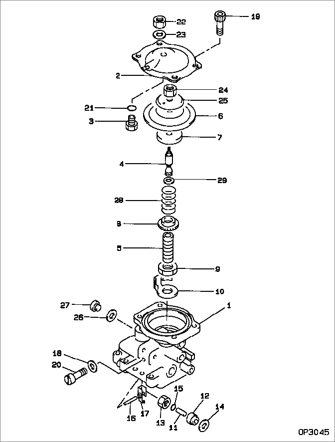
| 000. | [01] | 09649-00650 | COMPENSATOR SUB-AS | |
| 001. | [01] | 09644-01220 | COVER SUB-ASSY, GO | 22703-6A020 |
| 002. | [01] | 09644-00540 | COVER SUB-ASSY, GO | 22703-54501 |
| 003. | [01] | 09621-60030 | STOPPER, TIMER SLI | 22658-64518 |
| 004. | [01] | 09646-50232 | R0D, PUSH | 22321-54491 |
| 005. | [01] | 09611-80160 | BUSHING, GUIDE | 22348-64360 |
| 006. | [01] | 19263-10010 | DIAPHRAGM | 22542-54260 |
| 007. | [01] | 09624-60020 | SHEET, PLUNGER SPR | 22143-54260 |
| 008. | [01] | 09611-80190 | BUSHING, GUIDE | 22348-54490 |
| 009. | [01] | 94905-04070 | NUT, HEXAGON | 90099-05156 |
| 010. | [01] | 09621-10070 | CLIP, TIMER | 22656-54490 |
| 011. | [01] | 09645-50090 | PIN, LEVER CONECTI | 22338-54120 |
| 012. | [01] | 09611-80020 | BUSHING, GUIDE | 22348-54121 |
| 013. | [01] | 09625-40021 | NUT, GOVERNOR SHAF | 22722-54120 |
| 014. | [01] | 94901-81680 | WASHER, COPPER PLA | 90099-01473 |
| 015. | [01] | 09604-90230 | O-RING | 22193-55031 |
| 016. | [01] | 09627-20040 | PIN, LEVER SUPPORT | 22526-54120 |
| 017. | [01] | 09629-50070 | LEVER SUB-ASSY, CO | 22308-54120 |
| 017. | [01] | 09629-50670 | LEVER SUB-ASSY, CO | |
| 018. | [02] | 09642-60110 | GASKET, DELIVERY V | 22149-6D450 |
| 018. | [02] | 09024-80010 | WASHER, DRAIN SCRE | 22378-76010 |
| 019. | [04] | 91518-06121 | BOLT, W/WASHER | 90091-20610 |
| 019. | [04] | 09644-90130 | BOLT, SOCKET | 22395-54263 |
| 020. | [02] | 09626-90032 | BOLT, GOVERNOR LIN | 22739-54120 |
| 021. | [01] | 09604-90180 | O-RING | 22193-54561 |
| 022. | [01] | 94905-04100 | NUT, HEXAGON | 90099-05181 |
| 023. | [01] | 90200-08211 | WASHER, PLATE | 90093-00802 |
| 024. | [01] | 90176-06361 | NUT, HEXAGON | 90092-20608 |
| 025. | [01] | 19263-30010 | WASHER, THRUST | 22549-17140 |
| 026. | [01] | 09024-10010 | WASHER, AIR BLEEDE | 22119-77020 |
| 027. | [01] | 09031-70130 | PLUG, SCREW | 22129-54120 |
| 028. | [1C] | 09649-20150 | SPRING, BOOST COMP | 22546-54490 |
| 028. | [1C] | 09649-20160 | SPRING, BOOST COMP | 22546-54491 |
| 028. | [1C] | 09649-20170 | SPRING, BOOST COMP | 22546-54492 |
| 029. | [1C] | 09649-30230 | SHIM, BOOST COMPEN | 22547-54493 |
| 029. | [1C] | 09649-30220 | SHIM, BOOST COMPEN | 22547-54492 |
| 029. | [1C] | 09649-30210 | SHIM, BOOST COMPEN | 22547-54491 |
| 029. | [1C] | 09649-30110 | SHIM, BOOST COMPEN | 22547-54266 |
| 029. | [1C] | 09649-30100 | SHIM, BOOST COMPEN | 22547-54265 |
| 029. | [1C] | 09649-30090 | SHIM, BOOST COMPEN | 22547-54490 |
| 029. | [1C] | 09649-30240 | SHIM, BOOST COMPEN | 22547-54494 |
Include in #3:
09600-02030
as COMPENSATOR SUB-AS
09649-00650
Cross reference number
| Part num | Firm num | Firm | Name |
| 09649-00650 | COMPENSATOR SUB-AS |
Information:
Installation Of 5N7710 Fuel Injection Lines Group
(1) Remove the fuel injection lines from each fuel injection pump to the fuel nozzles. Remove the through-the-head adapter for each set of fuel lines. (2) Put an 8M4437 Seal on each 5N7730 Adapter (1). Install a new 5N7730 Adapter (1) in each bore where the former adapters were removed. Use a 9L9814 Nut (2) on each stud to fasten the adapters in position on cylinder head (3).(3) Install all of the 5N7717 Fuel Lines (4). Use a 5P9795 Seal between each line (4) nut and adapter (1), then use a 5P2060 Seal (5) at the other end of each line (4) nut and the nozzle. (4) Use a 5P9267 Seal between each nut (6) and its injection pump, and use a 5P9795 Seal between each nut (7) and adapter (1), and install the new fuel lines. Fuel lines are as follows: 5N7711 (8), 5N7712 (9), 5N7713 (10), 5N7714 (11), 5N7715 (12) and 5N7716 (13). Tighten all fuel line nuts to 40 7 N m (30 5 lb.ft.).(5) Use 8F1179 Clip (14) with the bolt and washer from the former fuel line clamp, to fasten fuel line (13) to the cylinder head.(6) Use the parts that follow to make a fuel line damper (shock cushion) for fuel lines (9) and (10) [section (A-A)]: 5N7732 Damper (15), 7B1597 Clip (16), 1D4538 Bolt (17), 5N4213 Spacer (18), 4N1278 Strip (19), 9S2299 Strip (20) and 1B5354 Nut (21) with a 9M1974 Washer. Use an S1617 Bolt (22) with a 9M1974 Washer to fasten strip (19) to the cylinder head.(7) At locations (A) and (B), use the parts that follow, to make a fuel line damper for fuel lines (8), (11) and (12); 4N1278 Strip, 9M1974 Washer, 9S2299 Strip, 1A9579 Bolt with 1B5354 Nut and two 5N7732 Dampers. Use an S1617 Bolt with a 9M1974 Washer to fasten 4N1278 Strip to the cylinder hood.Installation of 5N7741 Fuel Lines Drain Group And Alarm Switch
(1) Install a 5K9243 Elbow (1) in each 5N7730 Adapter (2). Connect five 5N7736 Tubes (3) and one 5N7737 Tube (4), then connect five 9L8557 Tees (5) and four 5N7740 Tubes (6) as shown. (2) Use two 5K6437 Clips (7) with S1617 Bolts and 9M1974 Washers, and three 8B6127 Clips (8) with existing bolts, to fasten this assembly into position. (3) Use two S1594 Bolts with 5M2894 Washers and 1D4717 Nuts to fasten 5N7733 Plate (9) to bracket (10) that is already on the engine.(4) Install 4M5317 Bushing (11), 5K9243 Elbow (12), 8B1931 Bushing (13) and 9L8496 Tee (14) with 9L8492 Plug (15) in 2N9768 Liquid Level Switch (16). Install 5N7739 Tube (17) in elbow (12), then use two S1616 Bolts, four 5P537 Washers, two 1B4330 Nuts and a 2B2404 Clip (18) to fasten switch (16), with tube (17), to plate (9) as shown. Vent passage in tube (17) must be open to the atmosphere at all times for the correct operation of this system.(5) Connect 5N7738 Tube (19) as shown, then